 |
BMe Research Grant |

|

Pál Vásárhelyi Doctoral School in Civil Engineering and Earth Sciences
Department of Structural Mechanicsk
Supervisor: Dr. Imre Bojtár
The mechanical effect of the material defects in
structural glass
Introducing the research area
Glass is considered one of the most popular materials in architecture for thousands of years. Due to the architectural trend of transparency, the use of glass is becoming more widespread. Thanks to the evolution of mechanics and the production technologies of glass it can be used not only for windows, but facade walls and roofs above large spaces.
The greatest disadvantage of the material is its brittleness. A small defect in the material structure can lead to immediate failure, with practically no post bearing capacity. That’s the reason why the investigation of microstructural defects is essential. My work concentrates on the analysis meso/micro defects in structural glass elements and how to consider their effects at the design level.
Brief introduction of the research place
The Department of Structural Mechanics is the most active research department at the Faculty of Civil Engineering at Budapest University of Technology and Economics.
Beyond the basic mechanical research, the Institution represents itself in several international disciplines such as topological optimization, biomechanics and material science.
History and context of the research
Glass – owing to its transparency – is one of the most popular building materials nowadays. The material itself has a very high strength, but most of the design standards impose very serious restrictions on the effective tensile strength of the glass, because the brittle failure reduces the security of the structural element.
The amorphous molecular structure accounts for the mechanical behavior of the material. Although the bound between the silicon and oxygen atoms is covalent – therefore a very strong bond between two atoms – it is dissimilar to a metallic bond, where an electron cloud keeps the metal ions together. The bond does not have any resistance to shear and the material is basically brittle. As a result, the stresses cannot relax in the area of a small local defect – the material does not become ductile – and great stress peaks occur. These local stress peaks could reach the strength of the material which can lead to immediate failure of the structural element.
This is why it is important to know the size, shape and distribution of the defects: we may get a view of what's happening during the failure. If we can reduce the amount of defects through various surface treatments, we may have a chance to increase the – macroscopic – effective strength of the given structural glass element.
Note that furthermore by glass I always mean soda-lime-silica.
Aims of the research
In Fig. 1 you can see four levels of the material glass testing. At the first, nanoscopic level we can analyze the bounding energies of the molecular structure. This analysis can be done by using molecular dynamic simulations. We can use the same method used to investigate a dynamic micro crack evolution in amorphous silica, done by Rountree et. al. (2007) with a 13 billion element model.
However, we are interested in a macroscopic level analyses in the first place that can be used in common design practices. Providing these analyses via molecular dynamics could be extremely difficult.
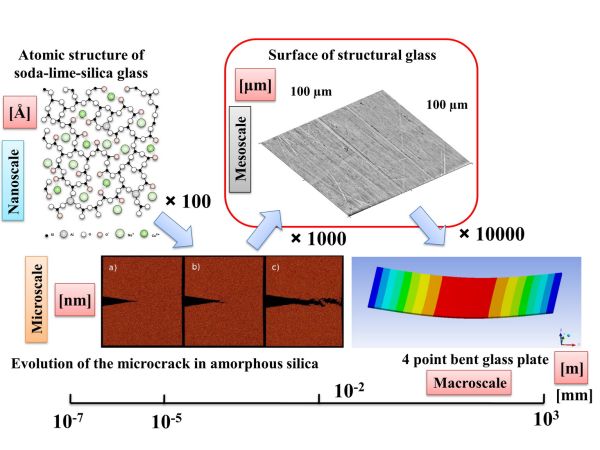
Figure 1: Multi-scale model of structural glass
A third type of analysis, the so-called mesoscopic experiment couples the macro scale with the micro scale. The present research aimed at carrying out the mesoscopic analysis to connect the micro and macro scales, and as a result to define macroscopic material properties on a continuum mechanics base.
Before starting the test, I had to divide the plates into regions. The first region – the largest one – is the surface of the plate. This region is exposed to weather therefore it has a time dependent surface topology. The second region is the edge – because of the edge finishing (grounding), this is the weakest region – cracks usually propagate from here. The third region is the volume of the plate, where inhomogeneities created during the manufacture remain in the glass.
I used AFM to map the surface and the edge and micro-CT to describe the volume defects.
Methods
Our examination can be divided into two major parts. First, I studied the mesoscopic defects of the glass plate and the strain peaks generated by them. This study was supported by FEM. In the second phase I used statistical methods to investigate the mechanical effect of volumetric defects. The aim was to derive a simple design guide capable of considering the extra strain caused by the inclusions.
AFM
Operation of the contact atomic force microscope is based on a very sensitive spring (called cantilever), which ends in a sharp tip. This tip is pushed against the sample surface with a well-defined lateral force. Then, the sample is moved by a precise piezoelectric scanner in lateral directions. The image builds up from vertical deflection of the cantilever, which is measured by laser reflection.
Micro-CT
To measure the inhomogeneities I have used micro-CT. Micro Computed Tomography is basically a commonly used 3D medical imaging technique. It makes 2D X-ray images, from which I can reconstruct a 3D model of the specimen with a special software. The images are recorded by one or more detectors. While the X-ray source moves around the specimen, the detector takes images in 5 degree steps. After the recording, the computer reconstructs the segments of the object, which can be used to build a 3D volume.
To eliminate distortions, I prepared column shaped specimens so that the radiation passes through the minimum possible amount of glass. I assumed that the images taken by the micro-CT are exact representations of the specimens.
Finite element model
To develop a finite element model I needed the real geometry of the specimens. I have used our own software to convert the data from the microscopes to a finite element input. I have used prescribed displacements as boundary conditions on the scaled model.
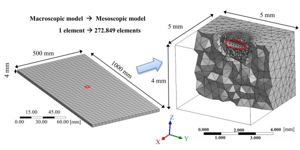
Figure 2: Finite element model developed to analyze inhomogeneities
After the calculation I have compared the strain peaks with the reference results calculated on a perfect model; this is how defined strain peak.
Statistical homogenization
The probability that the worst defect is at the point of maximal stress – calculated with a homogeneous material – is approximately zero. The aim of the analysis is to find a stress limit according to Eurocode-based design methods which will not be exceeded with a 95% probability.
First we have to integrate the probability density function of the stress peaks so the result should be 0.95, only the upper integration limit is unknown in the equation.
During the manufacturing of the float glass the company records the spatial and the size distribution of the defects, but the shapes remains unknown. However, the stress peak generated by the inclusions is primarily a function of shape, and not the size. As a result, I have to transform the original four random variables (three spatial, one shape) to one stress peak random variable. The transformation was done numerically using Monte Carlo simulation.
Results
Matching the division of our research work, I have divided the presentation of results into two parts as well. First, I describe the strain disturbances caused by the mesoscopic defects, and next I continue with defining a statistically based factor that describes the mechanical effects of volumetric imperfections in the glass plate. This factor can be used to provide guidelines and recommendations to minimize the effect of inclusions.
Effect of the surface scratches
|
|
|
|
|
Production +7.8 % |
Processing +36.59 % |
3 years of use +70.11% |
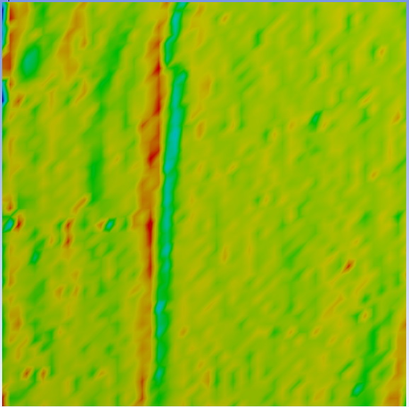
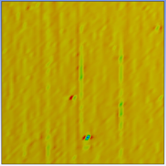
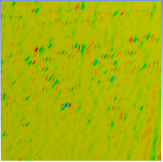
Figure 3: Peak results on the surface
Apart from a few very shallow – a few nanometres deep – scratches (Fig. 3), the glass specimen sampled right after the production (Guardian Hungary Co. Ltd.) was nearly flawless.
The specimen in the second column originates from a processing factory (OROSházaGLAS Ltd.). The surface of the specimen contain significantly more and deeper scratches, but it is not the scratches but the tiny pits that cause the strain peaks.
In the third column, a glass surface can be seen after having been used for three years as a facade. The nano scratches vanish but small pits appear. On the images taken from the numerical calculations, small pits – caused by weather – could be recognized which generate the major strain peaks.
The process could be explained by environmental corrosion. Fig. 4 shows further peak results as a function of time.
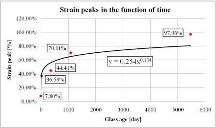
Figure 4: Peaks as a function of the age of surface
Edge processing related defects
The goal of this inspection is to compare the strain peaks caused by various edge finishing technologies. Generally, the edges of structural glass plates get a ground finishing, but upon request the manufacturer also polishes the edges after the grounding. I intended to clarify the potential benefits of edge polishing from the mechanical point of view.
|
|
|
|
Grounded +352.46% |
Polished +157.21% |
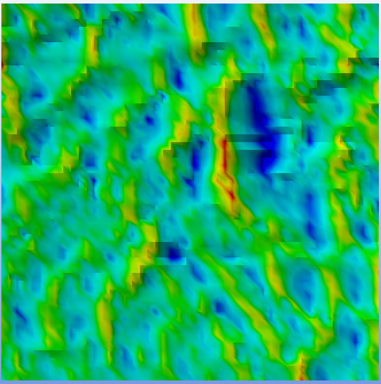
Figure 5: Peaks on the edge depending on finishing
Fig. 5 shows that the polished edge is much more even, and the stress increment is much lower than on the ground edge. As a conclusion, we can say that the polished edge finishing can reduce the strains on the edge by nearly 200%, thus it increases the effective strength of the structural element.
Inhomogeneities of the volume
We used a Skyscan 1172 micro-CT for the tests. The bubbles in the glass have a spheroidal shape (Fig. 6). The reason is that the bubbles which originally have sphere shape in the 1600°C melt – because of the hydrostatic state – extend along the axis of the draw during the floating manufacturing process. This arranges the longer axis of the spheroid parallel to the floating direction.
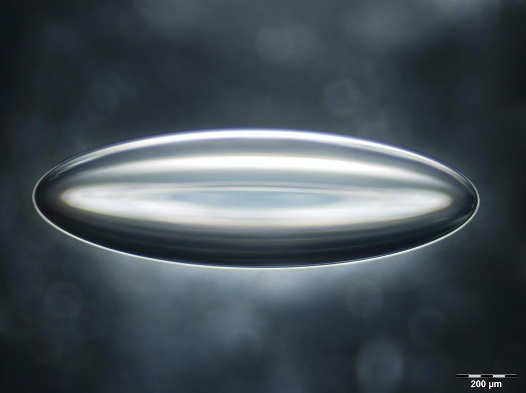
Figure 6: Bubble in the glass – optical image
Based on the database received from the manufacturer we could determine the spatial density functions (Fig. 7). With further optical microscopic measurements we could determine the distribution of the ratio of the two main axes.
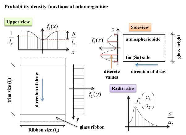
Figure 7: Probability density functions of the defects (three spatial, one shape)
This is very important because the strain peak depends on this ratio. We examined glass plates with different sizes based on the process described in the “Methods” part. We can see on Fig. 8 that the factor exhibits a size effect; the bigger the plate the more likely that it will contain a “sharper” imperfection.
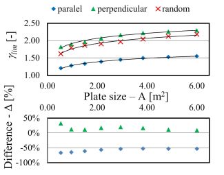
Figure 8: Factoring coefficient with respect to plate size
Our research has shown that if we choose the load in parallel with the longer axis of the inclusions as an average, we can reduce the extra stress caused by the imperfections by 50%. We have also introduced several different methods to minimize the effect of volumetric imperfections. Further results are published in the literature (Molnár et al, 2012).
Expected impact and further research
I use the material properties derived from the continuum-based mesoscopic analysis in a hybrid discrete and finite element model. The goal of this model is to trace the failure of tempered and annealed glass plates caused by different loads. We plan to verify our numerical model with an experiment using high-speed camera and a photoelastic investigation We execute these examinations in a cooperation with the Technical University of Denmark
The committee "TUD COST Action TU0905 Structural Glass" working on the European Standard (Eurocode) on the design of structural glass found our work worthy for further research, and enrolled the subject in the major topics of the work-group dealing with the determination of the strength of structural glass.
List of publications
MOLNÁR G., BOJTÁR I., The effects of the manufacturing inhomogeneities on strength properties of float glass. Mechanics of Materials, 2012, “Submitted”
MOLNÁR G., VIGH L. G., STOCKER GY., DUNAI L., Finite Element Analysis of Laminated Structural Glass Plates With Polyvinyl Butyral (PVB) Interlayer. Periodica Polytechnica Civil Engineering, Vol. 56, No. 1, pp. 35-42, 2012
MOLNÁR G., Effect of the Mesoscale Defects on the Strength Properties of Structural Glass, COST Training School “Structural Glass” Student Colloquium, Ghent, Belgium, pp. 15-18, 2012 (ISBN: 978-94-6197-029-9)
MOLNÁR G., MOLNÁR L.M., BOJTÁR I., Preparing a comprehensive analysis of the mechanical classification of structural glass, Materials Engineering - Materiálové inžinierstvo, Vol. 19, pp. 71-81, 2012
MOLNÁR G., MOLNÁR L.M., BOJTÁR I., Multi-Scale Analysis of Structural Glass, Imaging of The Mesostructure, Journal of Material Testers, Vol. 21, No. 3-4, pp. 1-14, 2012
MOLNÁR G., BOJTÁR I., Solution of 1D Finite Element Problems With Explicit Time Integration, Architectonics and Architecture, Vol. 40, No. 1, pp. 5-32, 2012
MOLNÁR G., VIGH L. G., STOCKER GY., Laminált üveglemezek hajlítási teherbírásának vizsgálata (in Hungarian), Magyar Építőipar, Vol. 62, No. 1, pp. 17-23, 2012
MOLNÁR G., Experimental and Numerical Examination of Laterally Loaded Laminated Glass, 28th Danubia-Adria-Symposium on Advances in Experimental Mechanics, Siófok, Hungary, pp. 263-264, 2011 (ISBN: 978-963-9058-32-3)
MOLNÁR, G., The Mechanical Behavior of Laterally Loaded Laminated Structural Glass, 11th Hungarian Conference on Theoretical and Applied Mechanics, Miskolc, Hungary, pp. 1-6. 2011 (ISBN: 978-963-661-975-6)
Useful links
BME Department of Structural Mechanics
Department of Electronics Technology
Journal of the American Ceramic SocietyMechanics of Materials
References
[1] Haldimann, M., Luible, A., Overend, M., Structural Use of Glass, Structural Engineering Document 10 IABSE, AIPC, IVBH pp. 85-106 (2008)
[2] Wörner, J.-D., Schneider, J., Fink, A.: Glasbau. Grundlagen, Berechnungen, Konstruktion. Springer-Verlag Berlin Heidelberg New York, p. 66 (2001)
[3] EN 1288-3:2000: “Glass in Building – Determination of the bending strength of glass – Part 3: Test with specimen supported at two points (four-point bending)”, CEN, Brussels; pp. 8-11 (2000)
[4] Rountree C.L., Prades, S., Bonamya, D., Bouchaud, E., Kalia, R., Guillot, C., A unified study of crack propagation in amorphous silica: Using experiments and simulations, Journal of Alloys and Compounds 434–435 (2007)
[5] Kern, W., Puotinen, D.A. Cleaning solutions based on hydrogen peroxide for use in silicon semiconductor technology. RCA Review, June, pp. 187-206 (1970)
[6] Henke, L., Nagy, N., Krull, U.J., An AFM determination of the effects on surface roughness caused by cleaning of fused silica and glass substrates in the process of optical biosensor preparation, Biosensors and Bioelectronics 17, pp. 547-555 (2002) (doi:10.1016/S0956-5663(02)00012-X)
[7] Molnár, L.M.; Mojzes, I.; Nanotechnológia (in Hungarian), Műegyetem Kiadó, 2007. Chapter 5, p. 75
[8] Hounsfield G. N.: Computerized transverse axial scanning (tomography): Part 1. Description of system, British Journal of Radiology, 46 , pp. 1016-1022 (1973), (doi: 10.1259/0007-1285-46-552-1016)
[9] Bartuška, M., and co-authors, 2001 Glass Defects Glass Service, Inc.
[10] Benedetti, A., Geotti-Bianchini, F., Fagherazzi, G., Riello, P., Albertini, G., De Riu, L., 1994 SAXS study of the micro-inhomogeneity of industrial soda lime silica glass. Journal of Non-Crystalline Solids. 167, 263-271
[11] Dyson, F.D., 1981 The potentials of ellipsoids of variable densities. Quarterly Journal of Pure and Applied Mathematics. 25, 259-288
[12] Eshelby, J.D., 1957 The determination of the elastic field of an ellipsoidal inclusion, and related problems. Proceedings of the Royal Society of London. Series A. Mathematical and Physical Sciences 241, 376-396
[13] Eshelby, J.D., 1959 The elastic field outside an ellipsoidal inclusion. Proceedings of the Royal Society of London. Series A. Mathematical and Physical Sciences 252 561-569
[14] Eshelby, J.D., 1961 Elastic inclusion and inhomogeneities. Progress in Solid Mechanics 2, 89-140
[15] Ferrers, N.M., 1877 On the potentials of ellipsoids, ellipsoidal shells, elliptic laminae and elliptic rings of variable densities. Quarterly Journal of Pure and Applied Mathematics. 14, 1-22
[16] Jin, Y., Wang, Z., Zhu, L., Yang, J., 2011 Research on in-line glass defect inspection technology based on Dual CCFL. Procedia Engineering. 15, 1797-1801. 10.1016/j.proeng.2011.08.334
[17] Liu, H.G., Chen, Y.P., Peng, X. Q., Xie, J.M., 2011 A classification method of glass defect based on multiresolution and information fusion. Int. J. Adv. Manuf. Technol. 56, 1079-1090. 10.007/s00170-011-3248-z
[18] Meng, C., Heltsley, W., Pollard, D.D., 2011 Evaluation of the Eshelby solution for the ellipsoidal inclusion and heterogeneity. Computers & Geosciences., 10.1016/j.cageo.2011.07.008
[19] Mura, T., 1987 Micromechanics of Defects in Solids: Mechanics of Elastic and Inelastic Solids. Kluwer Academic
[20] Peng, X., Chen, Y., Liu, H., Xie, J., Gu, C., 2011 An online defect classification method for float glass fabrication. Glass Technology - European Journal of Glass Science and Technology Part A. 52 (5) 154-160
[21] Peng, X., Chen, Y., Yu, W., Zhou, Z., Sun, G., 2008 An online defects inspection method for float glass fabrication based on machine vision. Int. J. Adv. Manuf. Technol. 39, 1180-1189. 10.1007/s00170-007-1302-7
[22] Routh, E.J., 1895 Theorems on the attraction of ellipsoids for certain laws of force other than the inverse square. Philosophical Transactions of the Royal Society of London. Series A. 186, 897-950