 |
BMe Research Grant |

|

Pál Vásárhelyi Doctoral School of Civil Engineering and Earth Sciences
BME Építőmérnöki Kar, Hidak és Szerkezetek Tanszék
Supervisor: Dr. Katula Levente
Single-Layer Free-Form Steel Reticulated Shell Structures
Single-layer reticulated shells sometimes referred to as grid shells became widespread in the last 15 years (Figure 1). Mainly the so-called free-from roof structures – with seemingly irregular shape and doubly curved mid-surface – became popular, thanks to software developed specifically for architectural design purposes. Because of the geometrical complexity, new questions arise in the areas of structural design and economic construction. The main goal of my research is to reveal the connection between the geometry of the shell and its structural behaviour. On the other hand, I focus on the joints that connect the members in the shell structure. I developed a numerical method suitable for comparing the structural behaviour of structures with different geometrical parameters and different joints.
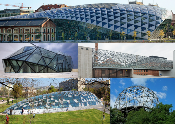
Figure 1. Single-layer reticulated shells recently built in Hungary: top: Bálna (Budapest, single-layer, free-form); middle: Páris Department Store glass ‘blob’ (Budapest, single-layer, free-form); Bridge in Zsolnay Cultural Quarter (Pécs, double-layer, source), bottom: Bikás park underground station (Budapest, single-layer, free-form, source); Xantus János observation tower (Balatonboglár, single-layer, sphere)
Brief introduction of the research place
The Department of Structural Engineering has been actively participating in state-of-the-art research in the field of Structural Engineering and Bridge Design. We also take part in several high priority projects as consultant, co-designer or independent inspector (e.g. Pentele bridge, Hárosi bridge). We mainly focus on applied research areas, such as thin-walled steel members, stability of steel members and structures, earthquake and prefabricated reinforced concrete beams. Experiments performed at our accredited Structural Laboratory provide valuable information on structural behaviour.
History and context of the research
Spatial structures may be classified into single- and double- or multi-layer reticulated structures. Double-layer structures prospered in the second half of the twentieth century. Even with a plane layout, they are capable of spanning large distances. Contrarily, a single-layer reticulated shell derives its strength from its curvature. Thus shallow shells can hardly prevent deflections perpendicular to their surface. This demonstrates, that the shape and geometry of a single-layer reticulated shell has a large influence on the structural behaviour.
Since the research of Gaudi, it is known that shell structures are economic if under frequent loads, only compression and tension forces develop in the structure. Gaudi determined the shape of structures after performing physical modelling: he built hanging models from chains, acting in pure tension. Inverting the obtained shape, we will get a structure in pure compression. Economic design of shell structures is based on this same concept, even today. Similar to Gaudi’s model, in computer-aided structural design, the optimal shape of reticulated shells are determined by form finding methods developed originally for tensile structures. Such a form finding method is dynamic relaxation [1], that was used to determine the shape and mesh of the British Museum Great Court roof structure [2], built in 2000, which is probably the most famous structure of its kind (Figure 2).

Figure 2. Finding the form with dynamic relaxation: British Museum Great Court roof structure (London, source); Amsterdam Maritime Museum (Amsterdam, source)
The research goal, open questions
Several studies deal with single-layer steel reticulated shells, but with simpler regular geometrical shapes – such as domes, barrel vaults or elliptic translational surfaces, while free-form structures rarely covered in scientific research papers. My research focuses on reticulated shells with a triangular mesh generated over a rectangular boundary. The question is, how to find the ideal form (shape or topography and structural height) and the ideal mesh density (topology).
The other key aspect of reticulated shells is the applied joints that connect the members [G6]. Double-layer shells are generally designed with simple joints, usually with only one bolt, that are capable to rotate, thus they are pinned. A shallow, single-layer shell can only bear loads perpendicular to its mid-surface, when the applied joints cannot rotate or only partially, in other words they are rigid or semi-rigid. This is generally realized by welded joints or joints with several bolts, that cost more in terms of labour and material. Hence, new joint systems needs to be developed, that may be adjusted to the varying curvature of the structure [3]. A given design is only economic, if the applied joint is just as rigid as required for the specific structure. Furthermore, design performance may be enhanced with the proper choice of the cross-section of the members. In practice, pipe sections are used, while cross-sections with only one axis of symmetry, such as rectangular or T shaped sections can be designed to have higher rigidity in the direction perpendicular to the shell mid-surface, than in-plane. The goal of my research is to design a semi-rigid joint for T cross-sections.
Methodology
In my research, a form finding method [2] similar to the previously introduced dynamic relaxation was used to generate the shape of the analysed shells. In this form finding method, instead of steel members, a system of springs pinned to each other is defined and loaded in each connection point. The method finds the equilibrium shape of this system with an iterative process (Figure 3). By changing the rigidity of the springs, various shapes can be generated (Figure 4), which are later used to compare their structural behaviour. R, the ratio of the spring stiffness values in different directions is the only relevant parameter of this process.
Figure 3. Form finding in Kangaroo
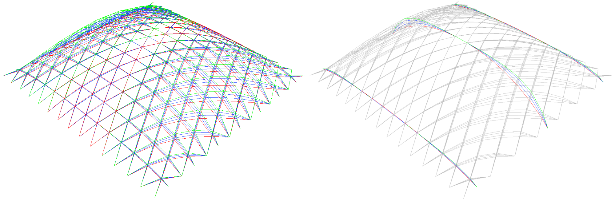
Figure 4. Results of the form finding procedure by varying the ratio of spring stiffness values in the two direction (R=0.3÷3)
The structural behaviour of a reticulated shell is the combination of both continuous shells (eg. concrete shells) and discrete beam structures. Therefore, its analysis is rather complex, and depending on the geometrical and stiffness properties they may fail in various ways [5,6] (Figure 5). One failure mode is shell-like buckling, similar to the deformation of a ping pong ball. This affects several nodes at a time, while other failure modes may occur even by the deformation of a single node of the mesh. These problems are investigated by the theory of stability.
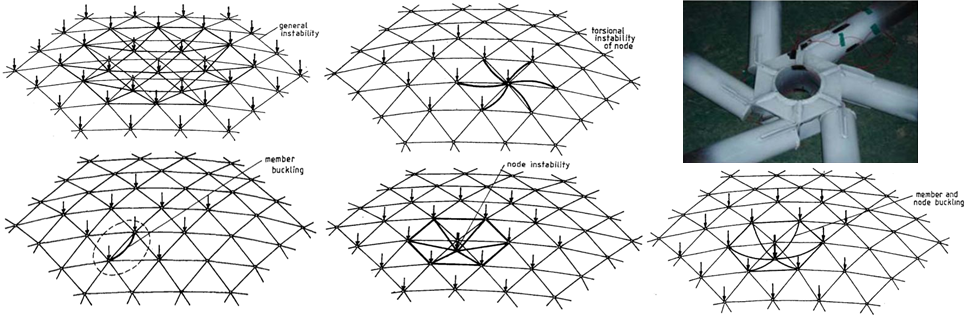
Figure 5. Possible buckling patterns or stability failure modes of single-layer reticulated shells [5]: top: shell-like buckling, rotated node buckling, rotated node buckling due to weak stiffeners [7]; bottom: member buckling, snap-through, interaction of the latter two
In my research, the load bearing capacity of structures were determined under several design load cases, where the loads were determined based on structural design codes. Non-linear finite element analyses were completed, and validated by analytical and experimental results [G2]. In these models, it was essential to consider the realistic behaviour of the structure by including the so-called imperfections. No standardized method of calculation of imperfections for reticulated shells exist. A subtype of imperfections is the geometric imperfection, such as inaccuracy due to the construction, which is inevitable. While the shape of the structures largely influences the structural performance of reticulated shells [6], even a small imperfection will significantly lower the load bearing capacity of the structure [G4]. Only a few research papers deal with the shape and amplitude of imperfections for reticulated shells [8,9].
I developed a parametric analysis process, which determines not only the load bearing capacity, but also the minimal required cross-sectional dimensions for structures with different shapes and with rigid and semi-rigid joints; thus the structures are designed with minimal weight. The method also allows determining, if a certain semi-rigid joint may or may not be effectively used for structures with a specific span.
Results
Our analysis performed so far focussed on structures with L=20 meter span [G2]. A relatively weak semi-rigid joint, the so-called “socket” joint [10] was applied, that connects pipe sections with a single bolt of 30 mm in diameter. The results show, that in the investigated range of shapes, similar shapes proved to have the best structural performance for any mesh density and height-to-span ratio, as it can be seen in the table of Figure 6. The the smallest section diameters (d) were obtained for structures with R=4÷6. As it can be seen on Figure 6, these shape have the least shallow parts.
It was shown, that in case of relatively small imperfections (L/1000), the socket joint may be applied for this span (L). This means, that for all cases included in the investigations, a shape could be found, that could be designed to bear the design loads. However, socket joints with smaller bolts (24 mm) can not be effectively designed for shallow shells with a dense mesh. Similarly, in case of high imperfections (L/300), the joint with 30 mm bolt cannot be used for shallow, dense meshes either.
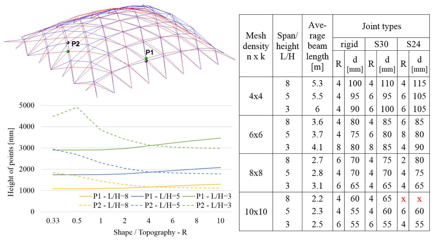
Figure 6. Comparison of structures with various geometry; left: geometrical properties of the shapes; right: analysis results in case of small imperfections (L/1000), where d is the cross-sectional diameter in the designed structure
As part of this research, a new bolted joint system was developed (Figure 7), that connects members with T cross-sections (such as in the roof of Milan Trade Fair). Compared to the previous socket joint, it is stronger and stiffer in the direction perpendicular to the shell surface, as two bolts are used in each connection. The joint system consists of 3 joints with different dimensions, as the system was designed to cover a wide range of spans.
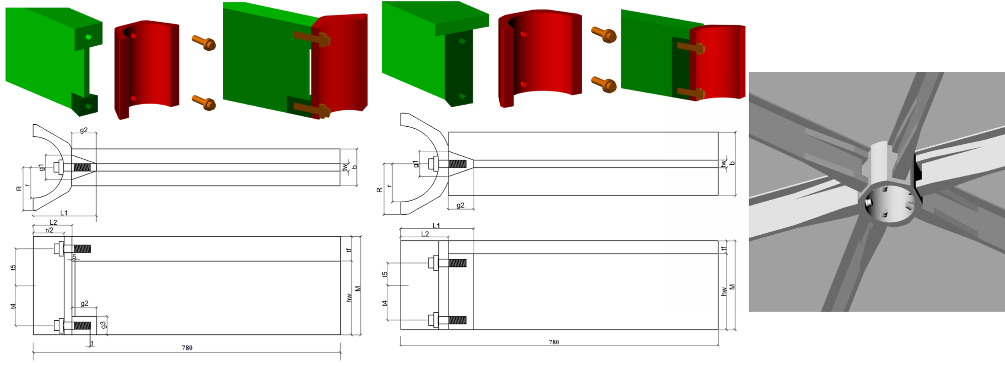
Figure 7. New joint system with two slightly different layout
To determine the stiffness of the joint, a more accurate finite element model was built with solid elements (Figure 8), modelling only one joint. The model considered pressure induced by the bolts, which causes the surfaces of the joint components to be are pressed to each other. The model is able to detect whether these surfaces will open up under loading. For this contact finite elements was applied. Based on a parametric analysis performed using this finite element model, the dimensions of the joint were determined: bolt diameter and the required dimensions of the joint component at the threaded part (Figure 7 dark green). The accuracy of the numerical model was proved by joint tests (Figure 9) performed in cooperation with the Space Structure Research Center of the Harbin Institute of Technology [G1] .
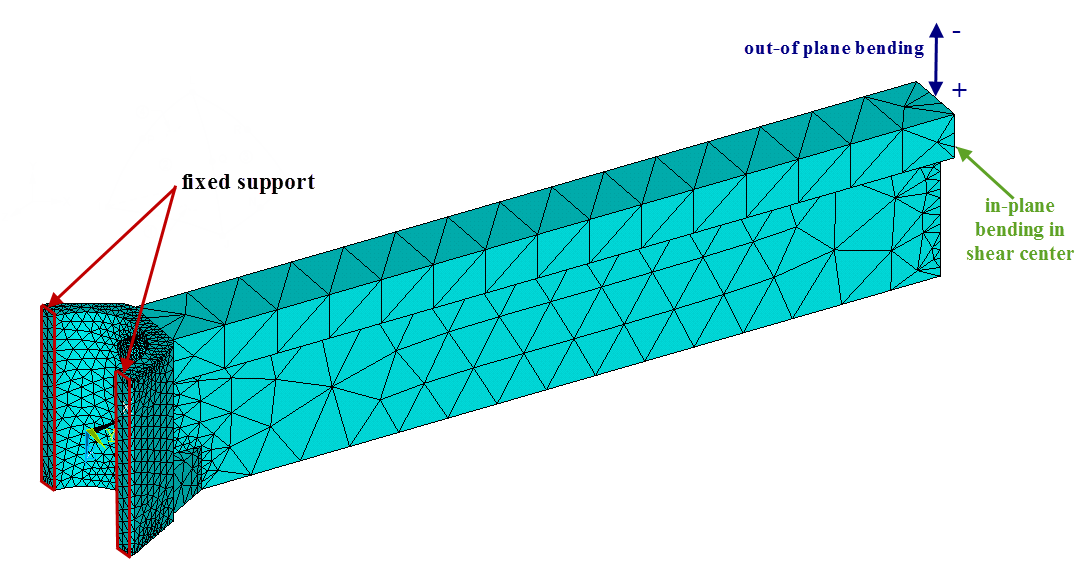
Figure 8. Finite element model of the T joint
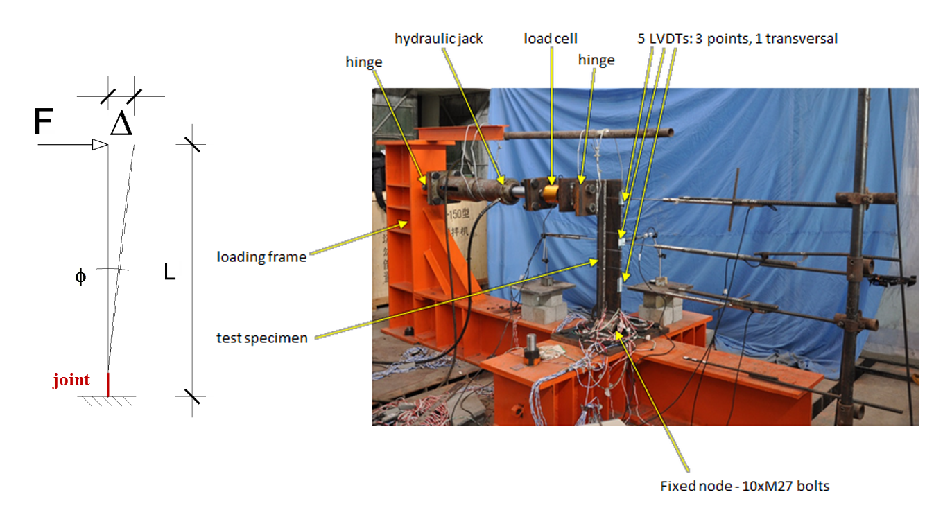
Figure 9. Experimental setup for determining the bending rigidity of the T joint
Expected impact and further research
In the next step of the research, the investigated range of spans will be extended to 20÷100 meters. The goal is to obtain conclusions similar to the ones above: to qualify the joint types and to compare various shapes. In case of smaller spans, the socket joint will be used, while for higher spans the stiffer T joints need to be applied. In the analysis of structures with T joints, the proper definition of imperfection will be a further challenge.
Publications, references, links
Publications
[G1] Gidófalvy, K., Katula, L., and Ma, H., A semi-rigid steel joint system for free-form shell structures with T sections, Periodica Politechnica, 2015 (in preparation)
[G2] Gidófalvy, K., Katula, L., and Ma, H., Semi-rigid joints in free-form grid shell structures, Journal of the International Association of Shell and Spatial Structures, 2015 (submitted)
[G3] Gidófalvy, K., Katula, L., Ma, H., and Fan, F., Semi-rigid free-form grid shells on rectangular plan, 7. European Conference on Steel and Composite Structures (Eurosteel 2014), Ed. Landolfo, Mazzolani, 2014
[G4] Gidófalvy, K., and Katula, L., Imperfection for the Buckling Analysis of Grid Shells, Proceedings of the Second Conference of Junior Researchers in Civil Engineering, 2013
[G5] Gidófalvy, K., Katula, L., and Mészáros, L., Behaviour study of single-layer steel grid shells based on numerical analysis, Proceedings of the Ninth FIB International PhD Symposium in Civil Engineering, Ed. Müller, Haist, Acosta, KIT Scientific Publishing, 2012, pp. 563–567.
[G6] Gidófalvy, K., and Katula, L., Effect of connection rigidity on the behaviour of single-layer steel grid shells, Proceedings of the Conference of Junior Researchers in Civil Engineering, 2012
[G7] Gidófalvy, K., Szabad formájú szerkezetek tervezése, MAGÉSZ Acélszerkezetek, Vol. 7, No. 2, 2010, pp. 41–45. (in Hungarian)
[G8] Gidófalvy, K., Szabad formájú szerkezetek tervezése, 14. Fémszerkezeti Konferencia, Göd, 2010, pp. 1–5. (in Hungarian)
Links
British Museum: Interesting description about form finding and theory of shells on the homepage of Professor Chris Williams, consultant for the British Museum
References
[1] Alamatian, J., Displacement-based methods for calculating the buckling load and tracing the post-buckling regions with Dynamic Relaxation method, Computers and Structures, Vol. 114–115, 2013, pp. 84–97.
[2] Williams, C.J.K. (2001) ‘The analytic and numerical definition of the geometry of the British Museum Great Court Roof’, 434–440, Mathematics & design 2001, Burry, M., Datta, S., Dawson, A., and Rollo, A.J. eds. Deakin University, Geelong, Victoria 3217, Australia.
[3] Kilian, A., and Ochsendorf, J., Particle-spring systems for structural form finding, Journal of the International Association for Shell and Spatial Structures, Vol. 46, No. 2, 2005, pp. 77–84.
[4] Stephan, S., Sánchez-Alvarez, J., and Knebel, K., Stabwerke auf Freiformflächen (Reticulated structures on free-form surfaces), Stahlbau, Vol. 73, No. 8, 2004, pp. 562–572.
[5] Kato, S., Fujimoto, M., and Ogawa, T., Buckling Load of Steel Single-Layer Reticulated Domes of Circular Plan, Journal of the International Association for Shell and Spatial Structures, Vol. 46, No. 1, 2005, pp. 41–63.
[6] Gioncu, V., Buckling of reticulated shells. State-of-the-art, Int. Journal of Space Structures, Vol. 10, No. 1, 1995, pp. 1–46.
[7] Kim, Y.J., Lee, Y.H., Kim, H., Bending Test of Welded Joints for Single-Layer Latticed Domes, Steel Structures, Vol. 8, 2008, pp. 357–367.
[8] Bulenda, Th., and Knippers, J., Stability of grid shells, Computers and Structures, Vol. 79, 2001, pp. 1161–1174.
[9] Fan, F., Yan, J., and Cao Z., Elasto-plastic stability of single-layer reticulated domes with initial curvature of members, Thin-Walled Structures, Vol. 60, 2012, pp. 239–246.
[10] Fan, F., Ma, H., Chen, G., and Shen, S., Experimental study of semi-rigid joint systems subjected to bending with and without axial force, Journal of Constructional Steel Research, Vol. 68, 2012, pp. 126–137.