|
|
BMe Research Grant |
|

Géza Pattantyús-Ábrahám Doctoral School of Mechanical Engineering
BME GPK, Department of Manufacturing Science and Engineering
Supervisor: Dr. Szalay Tibor
Extension of Empirical Specific Cutting Force Model for the Process of Fine Chip-removing Cutting
Introducing the research area
Topic of my PhD research is the experimental description and modeling of machinability based on the energetic parameters of mechanical cutting processes, focusing on precision and micro-cutting of conventional and high strength structural materials.
Brief introduction of the research place
I have completed my PhD researches at the Department of Manufacturing Science and Engineering, BME, under the supervision of Dr. Tibor Szalay. Scientific work of the Department is focused on classic and modern manufacturing methods, including the review of the state of the art, development and research of up-to-date technologies. This knowledge is being materialized through former and ongoing domestic (OTKA), EU supported multilateral joint research, bilateral (TéT) projects and industrial cooperation.
History and context of the research
Research and description of mechanical cutting processes dates back to the early years of the XX. century [1]. One of the most important research topics is the machinability of materials. Machinability is a non-standard definition, which describes how can a material be processed by cutting under given technological circumstances [2, B1].
Chip formation or cutting is the combined result of controlled fracture in the machined material and plastic deformation of chip. From this point of view, machinability reflects on the mechanical behavior of solid materials based on properties of material structure and cutting parameters. These circumstances collectively define the energetic characteristics of cutting, namely the cutting forces and cutting energy (or power). Milestones of cutting force research and interpretation are the models of:
-
Ernst and Merchant, based on the definition of shear plane of chip (1941) [3];
-
Kienzle and Victor, who created empirical force models based on specific cutting force (1957) [4].
The Kienzle-Victor model is commonly used in the practical industry due to its effectiveness, general and easy-to-use nature. Nevertheless, this model efficiently takes the phenomena of size effect into account: this means, the model can handle the nonlinear characteristics of cutting forces along the geometrical parameters of chip section.
There is an increasing demand for precision and micro-machining in parts manufacturing. Chip section parameters can have a scale of a few micrometers, which is identical to the scale of grain size of general structural materials (e.g. steels). Therefore, size effect has a crucial impact on the cutting process [5]. This needs to be accurately modeled in order to create effective predictions and suggestions of process parameters.
The research goal, open questions
Chip formation is a combined result of the following phenomena:
-
Fracture of material: as mechanical stress exceeds the tensile strength of the machined material, chip formation begins (Fig. 1/c).
-
Plastic deformations: the chip is deformed on the rake surface of cutting tool, but there are some minor deformations on the machined surface as well (Fig. 1/a and 1/b).
-
Elastic deformations: pressure on the machined surface does not reach the yield strength of the material. As pressure relaxes, the surface area recovers and thus, it will rub the flank surface of the cutting edge (Fig. 1/a).
Deformations and elastic recovery of the machined surface area are called ploughing effect, and it does not include any chip formation. This leads to the concept of minimum chip thickness (hm): there is an extreme rate of uncut chip thickness (h), where no chips are formed, but mechanical contact between part and tool still occurs. Therefore, hm can be interpreted as a lower limit of feed rate [6].
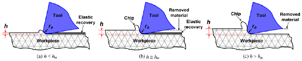
Figure 1. Machining process and minimum chip thickness [6]
Miniaturization is a spreading trend in parts manufacturing. This means the collective decreasing of nominal part size and tolerance [7]. Cutting parameters need to be aligned to these requirements, which causes the miniaturization of chip thickness.
The question is: what kind of practical model can interpret the machinability of materials so that the following requirements are met:
-
The model is valid for an extended range of cutting parameters, even in extreme scales;
-
The model can provide additional information on the quality of material deformation (shaping);
-
The model can define crucial technological limits of precision and micro-cutting, such as minimum chip thickness.
Methods
Defining the modeling method
A model based on the specific cutting force can meet the requirements above. The k-diagram: the specific cutting force (k) as per the uncut chip thickness (h) can expressly represent the size effect as well (see Eq.(1) and Fig. 2). This can be presented as continuous train of lines in the logarithmic system, where the different characteristics of lines suggest that different kind of material deformations occurred. [B2] Such multi-sectioned models can already be found in scientific literature [2]. However,
-
these model not at all or merely hypothetically join the technological domains of conventional (h > 0,01 mm) and fine (h ≤ 0,01 mm) chip-removal [8];
-
they are only valid for the process of fine chip-removal specifically [9].
k = F / (h ∙ b) = k1 ∙ hx + constant (1)
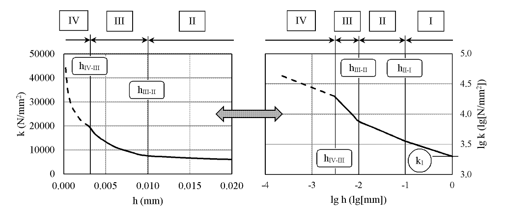
Figure 2. The k-diagram: sections and boundary chip thicknesses [B2]
Defining the method of experiment
Section boundaries of the k-diagram can be defined by boundary chip thicknesses (Fig. 2). Precise identification of such boundary chip thicknesses and the exact characteristics of each sections requires a fine resolution of the examined chip thickness domain. I choose face milling as the method of cutting experiment by considering the following advantages:
-
it is a general, commonly applied cutting process in parts manufacturing;
-
due to the kinematics of face milling, the domain of uncut chip thickness spreads from zero to an upper limit created by the fz feed rate per cutting edge (Fig. 3/b). Therefore, the only limit of resolution is the measuring frequency.
Force measurement was carried out applying a piezoelectric sensor along 3 fixed coordinate directions (X, Y, Z – see Fig. 3/b and Fig. 4/a). I performed face milling using a single-edged milling cutter (Fig. 3/a).
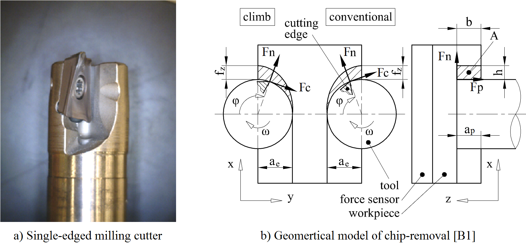
Figure 3. Geometrical model of face milling with single-edged cutter
Design of experiment, defining the evaluation method
My cutting experiments aimed at identifying a suspected new section and boundary chip thickness in the k-diagram. However, for my design method there was only hypothetical scientific information to base on [9,10,11,12,13,14,15]. Thus, I started with a full factorial design of experiment. The factors (cutting parameters) and their range were:
-
cutting speed: vc = 50…150 m/min;
-
feed rate per cutting edge: fz = 0.01 … 0.16 mm/edge/rotation;
-
depth of cut: ap = 0.5 … 2.0 mm;
-
kinematic direction of cut: DIR = climb (down-milling), conventional (up-milling) (Fig. 3/b).
The test piece was made of S960QL high strength structural steel which was selected for its high homogeneity of material structure.
Creation of Kienzle-type models require special evaluation method. Such method was already ready-to-use: linear regression was applied to fit the model function on the measured data (all transformed into logarithmic system, based on Eq.(1) and Fig. 2) [B4].
I applied the corrected standard sample deviation (CSSD) as an indicator of the model’s reliability. CSSD was defined with reference to the measured data, where the mean was calculated from the model. Sample sizes (the set of measurement) was defined by the measured number of milling tool rotations. Data acquisition and calculations required special software, which I developed in LabView.
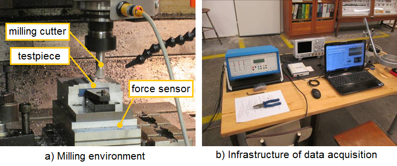
Figure 4. Environment of experiment
Results
New boundary chip thickness for fine chip-removing cutting
Machining forces are defined in a coordinate system, which is attached to the cutting edge. The force components are: main force (Fc), normal force (Fn), passive force (Fp) (Fig. 3). Means of uncut chip thickness (h) and uncut width of chip (b) can be approximated from the nominal path of the cutting edge. Following the calculation of specific forces, a k-diagram can be modeled (Fig. 4). [B3]

Figure 4. Statistical model of the k-diagram (fitted on data of a specific measurement) [B2]
Scientific literature defines boundary chip thicknesses at 0.1 mm and 0.01 mm, which are also identifiable in my measured data. However, a new boundary chip thickness can be observed in the domain of
h < 0.01 mm. As a first step of evaluation, I defined the mean of the new boundary chip thickness regardless to the cutting parameters. The existence of the new boundary chip thickness is confirmed by statistics, as seen on Fig. 4 and 5/a. [B2]

Figure 5. Boundary chip thicknesses [B2]
Correlations between boundary chip thicknesses and cutting parameters
ANOVA of measured data revealed, that the fz feed rate has a significant impact on the location of boundary chip thicknesses based on current data. Correlation between boundary chip thicknesses and fz can be reliably modeled by a response surface, which concludes that increasing of fz causes the exponential increase of mean boundary chip thicknesses (Fig. 5/b). [B2]
About deformation processes and defining a critical chip thickness
The following implications and hypothesis can be stated according the sections of the k-diagram, shown in Fig. 1, 2 and 4 [B2]:
-
Section I: cutting using macro chip geometry, where most of the cutting energy is absorbed by chip formation (Fig. 1/c);
-
Section II: ratio of the cutting energy absorbed by plastic deformation at the tip of the edge has been increased, yet there is a stable chip formation (interaction between Fig. 1/b and 1/c);
-
Section III: cutting using fine chip geometry, where cutting energy absorption due to ploughing effect notably increases, and chip formation becomes unstable (Fig. 1/b);
-
Section IV: ploughing effect dominates the process, material removal is negligible (Fig. 1/a).
Sections III and IV do not appear as separated sections in scientific literature, therefore, the boundary chip thickness between these sections cannot be identified. Given the fact, that the minimum chip thickness defines the lower limit of stable chip formation [16], I propose to introduce the definition of critical uncut chip thickness as the absolute lower limit of material removal.
Expected impact and further research
I have developed a methodology (including the software support thereof) to define the specific cutting force, which can be efficiently realized in practical industrial circumstances. I have defined a new section of the k-diagram, which supports the idea of applying the k-diagram for material technology purposes. Regarding the identification of deformation phenomena of chip and machined surface, I plan new experiments with different cutting technologies (precision face turning, micro-drilling, micro-milling).
Definition of critical uncut chip thickness is still hypothetical. Machining in this technological scale may alter the mechanical properties, most prominently the hardness of the surface area. This phenomena may be exploited for surface engineering of micro-geometries. I intend to carry out specialized experiment in this field as well.
Publications, references, links
Publications:
[B1] Biró I, Czampa M, Szalay T: Experimental Model for the Main Cutting Force in Face Milling of a High Strength Structural Steel, Periodica Polytechnica – Mechanical Engineering, 59(1): 16–22. (2015), DOI: 10.3311/PPme.7516
[B2] Biró I, Szalay T: Extension of empirical specific cutting force model for the process of fine chip-removing milling. International Journal of Advanced Manufacturing Technology, Online First edition: 1–9. (2016) - Impact factor: 1,568 (28.06.2016), DOI: 10.1007/s00170-016-8957-x
[B3] Biró I, Szalay T, Markos S: Machinability of S960QL high strength structural steel: energetic description of cutting at small chip-thickness in face milling. International Conference on Innovative Technologies (IN-TECH 2013): 237–240. (2013), ISBN: 978-953-6326-88-4
[B4] Bíró I, Szalay T: Forgácsolhatóság kísérleti vizsgálata S960QL nagy szilárdságú acélnál (in Hungarian). Technika Műszaki Szemle, 55(12): 18-22. (2012)
Links:
References:
[1] Szalay T: Modeling in Metal Cutting Theory. Barišić, B. ed. Concurrent Product and Technology Development, 85–102., Kastav: Fintrade and Tours (2009), ISBN: 978-953-96899-9-3
[2] Bali J: Forgácsolás. Budapest: Tankönyvkiadó (1985), ISBN: 963-18-0806-8
[3] Ernst H, Merchant ME: Chip formation, friction and high quality machined surfaces. Transactions of American Society for Metals, 29: 299–378. (1941)
[4] Kienzle O, Victor H: Spezifische Schnittkräfte bei der Metallbearbeitung. Werkstattstechnik und Maschinenbau, 47: 22–25. (1957)
[5] Takács M, Verő B: Material Structural Aspects of Micro-Scale Chip Removal. Material Science Forum, 414–415: 377-342. (2003), DOI: 10.4028/www.scientific.net/MSF.414–415.337
[6] Aramcharoen A, Mativenga PT, Size effect and tool geometry in micromilling of tool steel. Precision Engineering, 33(4): 402–407. (2009), DOI: 10.1016/j.precisioneng.2008.11.002
[7] Wojciechowski S: The estimation of cutting forces and specific force coefficients during finishing ball end milling of inclined surfaces. International Journal of Machine Tools and Manufacture, 89: 110–123. (2015), DOI::10.1016/j.ijmachtools.2014.10.006
[8] Altintas Y, Jin X: Mechanics of micro-milling with round edge tools. CIRP Annuals – Manufacturing Technology, 60(1): 77–80. (2011), DOI:10.1016/j.cirp.2011.03.084
[9] Campatelli G, Scippa A: Prediction of milling cutting force coefficients for aluminum 6082-T4. Procedia CIRP, 1: 563–568. (2012), DOI: 10.1016/j.procir.2012.04.100
[10] Jin X, Altintas Y: Prediction of micro-milling forces with finite element method. Journal of Material Processing Techology, 212(3): 542–552. (2012), DOI: 10.1016/j.jmatprotec.2011.05.020
[11] Ko JH, Yun WS, Cho DW, Ehmann KF: Development of a virtual machining system, part 1: approximation of the size effect for cutting force prediction. International Journal of Machine Tools and Manufacturing, 42(15): 1595–1605. (2002), DOI: 10.1016/S0890-6955(02)00137-2
[12] Srinivasa YV, Shunmugam MS: Mechanistic model for prediction of cutting forces in micro end-milling and experimental comparison. International Journal of Machine Tools and Manufacturing, 67: 18–27. (2013), DOI: 10.1016/j.ijmachtools.2012.12.004
[13] Balogun VA, Mativenga PT: Impact of un-deformed chip thickness on specific energy in mechanical machining processes. Journal of Cleaner Production, 69: 260–268. (2014), DOI: 10.1016/j.jclepro.2014.01.036
[14] Liu K, Melkote SN: Material strengthening mechanisms and their contribution to size effect in micro-cutting. Journal of Manufacturing Science and Engineering, 128(3): 730–738. (2005), DOI: 10.1115/1.2193548
[15] Afazov SM, Ratchev SM, Segal J, Popov AA (2012) Chatter modeling in micro-milling by considering process nonlinearities. International Journal of Machine Tools and Manufacturing, 56: 28–38. (2012), DOI: 10.1016/j.ijmachtools.2011.12.010
[16] Ramos AC, Autenrieth H, Strauß T, Deuchert M, Hoffmeister J, Schulze V: Characterization of the transition from ploughing to cutting in micro machining and evaluation of the minimum thickness of cut. Journal of Materials Processing Technology, 212(3): 594–600. (2012), DOI: 10.1016/j.jmatprotec.2011.07.007