|
|
BMe Research Grant |
|

Doctoral School of Electrical Engineering
Department of Broadband Infocommunications and Electromagnetic Theory
Supervisor: Dr. Horváth Péter
Numerical Validation of Portable Wireless Communication Devices
Introducing the research area
Portable wireless communication devices (e.g. mobile phones, wearable multimedia and medical devices etc.) have to comply with strict regulations in order to enter the market. Among these are multiple standards based compliance measurements. There have been numerous approaches recently to interchange certain measurements with computer based numerical simulations. A precondition for this, however, is making sure that the real world device and the simulated one show identical (electromagnetic) behaviors. My research topic is to find an efficient and reliable validation method for the numeric model of device under test with respect to specific absorption rate (SAR).
Brief introduction of the research place
The research is carried out in cooperation between two laboratories of the Department of Broadband Infocommunication and Electromagnetic Theory, namely the Digital and Optical Communications Systems (DOCS), and Electromagnetic Simulation and Design (EMTLab) laboratories. Both laboratories have decades of experience in the field of research. They have published numerous papers at international conferences and journals, respectively. Also, both laboratories took part in various projects funded nationally (e.g. OTKA and TÁMOP) and by the European Union.
History and context of the research
Portable wireless devices need to comply with numerous regulations in order to enter the market. Of them, the most important is the compliance with electromagnetic exposure to human body. According to the standard [1], exposure is determined by the specific absorption rate (SAR). If SAR exceeds the limit described in the standard, the device is not allowed to be commercially distributed since it may be harmful to human health. As the measurement process required by current standard is very compound and expensive, there are only few laboratories that can carry it out in Europe. Moreover, the next generation (5G) mobile devices and the expanding market of internet of things (IoT) devices [2] will use millimeter waves as means of communications [3]. This extends the current frequency ranges used by such devices. The measurement procedure gets more complicated on these frequencies, thus standardization bodies tend to replace certain measurements with computer based numerical simulations [4–7]. Further advantages of numerical simulations is that compliance with exposure limits can be monitored throughout the design process of devices, and avoiding design failures can significantly reduce both time to market and design costs.
The research goals, open questions
To replace exposure compliance measurements with simulations, a numerical model of the device under test has to be elaborated. But how can we trust that a particular numerical model conforms to the real world device? Generally, if certain measurements on the device under test comply within a given tolerance with the simulated values of the same measures, then the numerical model can be considered valid. Such a process is called the numerical validation of the device under test. However, numerical validation as laid down in current standards requires nearly the same measurement equipment and environment as the complete compliance measurement without simulation. The aim of our research is to find a cost effective and reliable numerical validation method.
Methods
I. Specific absorption rate measurement, model validation
Measurement of specific absorption rate is carried out using a specific anthropomorphic mannequin (SAM). The SAM is manufactured to have identical radio frequency properties to those of human head. This can be achieved by filling the SAM with a liquid having the same dielectric constant and conductivity as the human head (the liquid substances are different for the various frequency bands). The device under test is placed and operated in the close vicinity of the SAM. In the meantime a precision positioning robot arm equipped with electric field sensors scans throughout the whole SAM. After measuring the electrical field in each measurement position, the SAR is calculated (usually averaged over a given volume). The apparatus used for the SAR exposure measurement of mobile devices is shown in Figure 1. Almost all equipment needed for the procedure is specific for this kind of measurement and are very expensive. Also, the measurement is needed to be carried out in an anechoic chamber – another big investment.
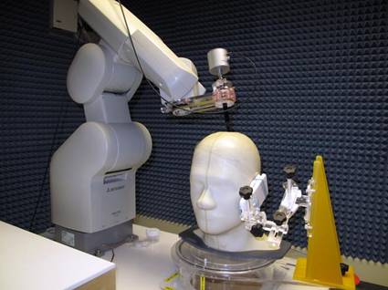
Figure 1: Apparatus for SAR exposure measurement (source: [8])
The aim of standardization bodies is to replace the above measurement process with numerical simulations. However, the numerical validation process does not simplify the measurements significantly. The validation only needs a simplified head phantom, which has a shape of a rectangular prism, but a precision positioning system equipped with electrical field sensor is still needed to measure the e-field in certain points. For the simulation, the numerical model of the simplified head phantom and device under test is needed. The measured and simulated e-field at certain points inside the phantom are compared with formulas according to the standard. As a result, the precision/uncertainty of the numerical model of the device under test is obtained.
II. Proposed validation method
Our approach to the validation procedure is different. In this case the one-port characteristic (e.g. input impedance, reflection coefficient etc.) of the devices’ antenna (which is responsible for the RF exposure) is investigated. The main reason is that an equipment for the one-port characteristic measurements is more affordable and also generally available for RF engineers. Our approach is based on the systematical perturbation of the near-field of the antenna by placing a dielectric control object at various positions in the vicinity of the device. Such a procedure is shown in Figure 2 for a 1 GHz planar inverted F (PIFA) antenna with a cube shaped control object. Viewing from above, the cube appears as a square (red object). Since the maximal current density is reached at the left hand side of the inverted F, it is practical to choose the scanning positions near that end of the antenna. According to our derived formula we can calculate the input impedance difference in the absence of the control object and also being placed at various locations. The formula shows that the impedance change observed is proportional to the e-fields existing inside the volume of the control object if it is absent or it is present. Thus the proposed validation method is capable to validate the distribution of the e-field indirectly. Consequently, in this case the measured and the simulated input impedance have to be compared.
Figure 2: View from above - positioning of the control object (red cube) on the surface of the device (demonstration of proposed scheme)
Results
Through a specific example we have shown in [S1] that there is a relationship between the change in the one-port characteristic and the SAR. The example showed that the one-port characteristic change is more pronounced if the control object is positioned at such places where the SAR is high in a flat phantom. We also derived an exact formula to quantify the (frequency dependent) one-port characteristic change (the formula is derived for the input impedance) in [S2]. An error measure was also derived in [S2] that shows that the precision of the input impedance measurement is proportional to the square of the e-field. Thus the input impedance change is a good measure to validate the e-field.
In order to validate our formula, we carried out a measurement with the setup shown in Figure 2. We used a 1 GHz PIFA antenna and a cube shaped control object. The free space input impedance, and the input impedance with the control object placed to different scanning positions were measured and simulated, respectively. In the simulation, the input impedance change can either be computed directly or from the e-field values via our derived formula in [S2]. The measurement results compared with the two types of simulation are shown in Figure 3. Furthermore, Figure 4 shows the measurement results compared to the impedance change calculated from our formula on a 2D grid. The 2D visualization is in good agreement with the scanning positions shown in Figure 2. From the results we can conclude that the measurement and the simulations show good agreement, which confirms our theory on the proposed validation method.
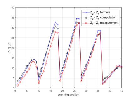
Figure 3: Measured and simulated impedance change in function of scanning position (proposed validation scheme)
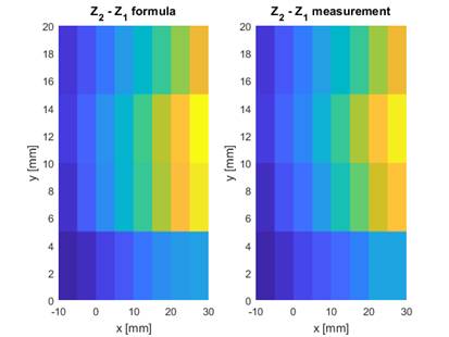
Figure 4: Measured and simulated impedance change in function of scanning position (proposed validation scheme) on a 2D grid, with color mapping
Expected impact and further research
We developed a validation scheme for portable wireless communication devices that is more cost efficient than the existing one proposed by current standards. The measurement equipment applied in this validation process is so affordable that it might be reasonable for even small companies and startups. Further research focuses on providing more direct validation method of e-field based on the one-port characteristics. Also, we aim at presenting additional measurement and simulation results to confirm that the method is feasible even for devices designed for millimeter wave communications. Hence, the proposed method can even be considered as a candidate for future numerical validation methods proposed by standards.
Publications, references, links
Publications:
[S1] B. Horváth, P. Horváth, Z. Badics, J. Pávó, and L. Csurgai- Horváth , “Computational Model Validation of Wireless Devices for SAR Evaluation,” 10th European Conference on Antennas and Propagation (EuCAP), Davos, Switzerland, April 10–15, 2016.
[S2] B. Horváth, Z. Badics, J. Pávó and P. Horváth, "Validation of Numerical Models of Portable Wireless Devices for Near-Field Simulation," in IEEE Transactions on Magnetics, vol. 53, no. 6, pp. 1–4, June 2017.
References:
[1] Determining the Peak Spatial-Average Specific Absorption Rate (SAR) in the Human Body from Wireless Communications Devices, 30 MHz - 6 GHz, Part 1: General Requirements for using the Finite Difference Time Domain (FDTD) Method for SAR and other Exposure Calculations, Draft IEC/IEEE 62704-1, June 2016.
[2] A. Gupta and R. K. Jha, "A Survey of 5G Network: Architecture and Emerging Technologies," in IEEE Access, vol. 3, no. pp. 1206–1232, 2015.
[3] J. Manyika, et al, THE INTERNET OF THINGS: MAPPING THE VALUE BEYOND THE HYPE, McKinsey Global Institute, McKinsey & Company, June 2015
other Exposure Calculations, Draft IEC/IEEE 62704-1, June 2016.
[4] A. Christ, M. Douglas, W. Kainz, and N. Kuster, “Standardized methods for the application of the FDTD method in numerical dosimetry,” 7th European Conf. on Antennas and Prop. (EuCAP), pp. 1974–1977, 2013.
[5] Determining the Peak Spatial-Average Specific Absorption Rate (SAR) in the Human Body from Wireless Communications Devices, 30 MHz - 6 GHz, Part 4: General Requirements for Using the Finite-Element Method for SAR Calculations and Specific Requirements for Modelling Vehicle-Mounted Antennas and Personal Wireless Devices, Draft IEC/IEEE 62704-4, November 2016.
[6] M. Siegbahn, G. Bit-Babik, J. Keshvari, and A. Christ, “An international interlaboratory comparison of mobile phone SAR calculation with CAD-based models,” IEEE Trans. Electromagnetic Compatibility, vol. 52, no. 4, pp. 804–811, 2010.
[7] V. Monebhurrun, Xi Cheng, and A. Rojatkar, “CAD Mobile Phone Model Calibration using Experimental SAR Data,” Radio and Antenna Days of the Indian Ocean (RADIO), September 21-24, 2015.
[8] http://wired.com