|
|
BMe Research Grant |
|

Hajdu Dávid
BMe Research Grant - 2018
II. Prize
![]()
Géza Pattantyús-Ábrahám Doctoral School of Mechanical Engineering Sciences
Department of Applied Mechanics
Supervisor: Dr. Insperger Tamás
Robust Stability and Control of Regenerative Machine Tool Vibration
Introducing the research area
Regenerative machine tool vibration is a dynamical phenomenon that appears during a non-abrasive machining operation, leads to large amplitude self-excited vibrations (Fig. 1.) and results in unacceptable surface quality. The research addresses the conditions which lead to the occurrence of these vibrations, their elimination, and the improvements to the current model considering the presence of dynamical uncertainties.
Figure 1. Milling operation recorded by a speed camera (8400 rpm).
Brief introduction of the research place
SIREN ERC research group was founded in 2013 and received funding from the European Research Council. At the time of its foundation three groups have been set up to provide accurate models on the chip formation process, examine the mechanical contact between components and identify the important factors that affect the spindle dynamics.
History and context of the research
The importance of machine tool vibration was recognized at the beginning of the 20th century, but the more sophisticated mathematical models describing these phenomena only appeared in the ‘60s [H1,H2]. Due to technology limitations, the first models were confined to simplified calculations. The onset of computer technology allowed deeper analyses and understanding of the underlying phenomena, the dynamics of machining. Nowadays, due to the extensive research on the topic many research papers have been published and solutions have been developed to predict the appearance of these vibrations or even to suppress them using active or passive vibration absorbers [H3].
To avoid these harmful vibrations, first we need to understand the reason of their occurrence and how they evolve during the machining process. As it can be seen in Fig. 1., the cutting edge of the tool periodically enters and exits the material and the cutting force results a periodic motion. The consequence of the relative displacement between the work piece and tool is a poor surface quality, and the extent will depend of the spindle speed during cutting. Since the surface of the work piece “remembers” past events, the geometry of the currently removable chip depends on past states, too. This explains for its name, regenerative effect, which is mathematically described by periodic delay differential equations. These models can lose stability, i.e. the amplitudes of vibrations keep increasing until the contact between the tool and work piece is lost. The phenomenon is called chatter. It results in an unacceptable surface finish, reduced tool life and, in extreme cases, damage to the machine components.
The research goals, open questions
Once the dynamical measurements and cutting experiments are completed, the so-called stability lobe diagrams can be constructed to provide a guide for the operator to select optimal machining parameters and avoid chatter. These diagrams are typically visualized on the plane of technological parameters, such as the spindle speed and depth of cut, and separate the domains where chatter can occur (unstable) or can be avoided (stable). For these calculations dynamical parameters and empirical cutting force characteristics have to be provided [H4]. These data can be determined by preliminary experiments, e.g., dynamical measurements can be performed by impact tests. By means of mathematical methods the stability lobe diagrams can be calculated (see Fig.4.) [H5].
Measurements are often loaded by noise, parameter fittings may be inaccurate [K1,K2,F4], empirical formulas are mere assumptions, and the models applied in calculations are often simplified ones. Due to these approximations, experimental chatter tests frequently do not match the preliminary calculations and fail to provide accurate predictions. This is one of the reasons why these techniques are still not widely utilized in industrial applications [F3].
To enhance the methods, we need to consider the uncertainties in the modeling process. Those systems that perform properly even in the presence of uncertainty are called robust systems. The aim of the research is to provide a robust technique which guarantees stable machining and avoids chatter even if uncertainties arise.
Methods
Based on our experiences and literature reviews it was found that the uncertainties of modal parameter estimations have significant effect on stability predictions [F4]. Most of the methods available in the literature are not capable of effectively handling the extensive calculation effort and therefore, they are either limited to small number of parameters or lead to unacceptably long calculation time [F1,K3]. Note that no robust method exists which is directly applicable to time-periodic and delayed differential equations.
Multi-frequency solution
To bypass these issues we utilized the uncertainties of frequency response functions (FRFs) and completely avoided modal parameter estimations [F1,F2,K3]. This way the uncertainty can be estimated directly from impact tests based on probabilistic calculations or upper/lower bound estimates. A measured FRF matrix is represented in Fig. 2., where ten individual measurements were performed in each directions (gray curves) and their average is indicated by black solid line. As it can be seen, the measurements are inaccurate, therefore the average in not sufficient to properly describe the dynamical behaviour. The so-called multi-frequency solution [H4,H6] is capable of determining the stability lobe diagrams from FRFs directly, but cannot consider their uncertainty.

Figure 2. Measured frequency response functions at the tool tip.
Structured singular value analysis
To consider uncertainty in predictions, structured singular value analysis can be applied (mu-analysis) [H7], that is a widely used and accepted technique in robust control. The dynamical model is represented in the M-Delta uncertain interconnection structure, which includes the uncertainty of the FRFs, too. Combination of the multi-frequency solution with the structured singular value analysis yields a computable formula to calculate the robust stability boundaries [F2,K4].
The standard mu-analysis, however, generally leads to lengthy calculations. To significantly speed up the process, we used a slightly conservative approximation provided by [H8], which reduced the calculation time comparable in magnitude to those required for conventional stability lobe diagrams without uncertainty [F2].
Results
Experiment- Robust stability of milling operations
An experimental setup is presented in Fig. 3. together with images of the produced surface quality both for stable (chatter-free) and unstable operations (chatter). Chatter tests are carried out with a regular two-fluted milling tool, with half-immersion down-milling operation.
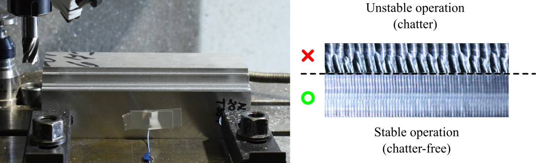
Figure 3. Experimental setup [K4].
Results presented in Fig.4. compare the theoretical calculations to experimental observations. The measured tooltip FRFs and the uncertainties are presented in Fig .2. Panel (a) in Fig. 4. show the dominant chatter frequencies. I can be seen that the deviation increases with increasing spindle speeds, indicating that the dynamical properties of the spindle change with the speed of rotation. Panel (b) shows the calculated robust stability diagram. While the conventional boundaries (black curves) are slightly inaccurate, the robust stability domain (below the red curve) represents a safe region, where almost all of the points were found to be stable. Green circles indicate stable operation, magenta squares denote marginal points and red crosses stand for unstable experimental points. The difference is often observed in experiments that underline the necessity of robust calculations [F4, K4].
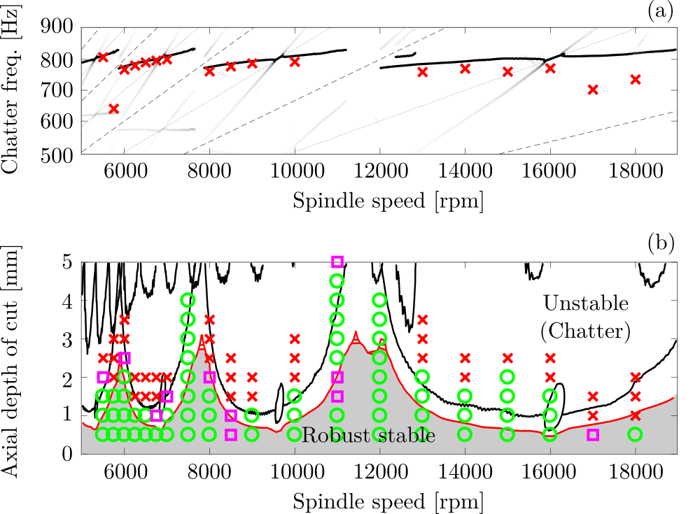
Figure 4. Experimental and theoretical stability boundaries: (a) Dominant vibration frequencies; (b) Robust stability lobe diagram (Experimental points: green circle - stable, magenta square - marginal, red cross - unstable) [K4].
Case study - Robust controller design for turning operations
These robust calculations can be improved further and can be implemented in robust controller designs. Active and passive vibration absorbers are often used by the industry [H3], however, due to time-delays and inaccuracies the applications are often not reliable. Design of a robust PD-controller in case of turning operations is presented in Fig. 5. The robust design of the control gains depend not only on the delays, but also on the uncertainty of the frequency response function matrix between the tooltip and actuating point of the controlled force [K5]. Utilization of the structured singular value analysis can help to select the robust control gains, as it is presented in the animation in Fig. 5. While the non-robust control gains result a large uncertainty domain (light gray), the robust controller can ensure stability, reduces the uncertain region and increases the domain of robust stable machining parameters (dark gray).

Figure 5. Mechanical model of turning operations with active vibration
absorber
(Three cases: I. no controller, II. non-robust controller, III. robust
controller) [K5].
Expected impact and further research
Experimental results clearly show that robust stability calculations play an important role in the predictions of stability of machining operations. Since industrial applications require a certain level of safety, robustness against uncertainties is an important feature of systems. Additionally to robustness, a further advantage is that the method requires relatively little calculation efforts and there is no need for model parameter estimation.
There are a several ways to extend the research. On the one hand, the conservativeness of the method should be reduced, and the technique can be extended to robust controllers designs for milling operations, on the other.
Publications, references, links
List of corresponding own publications.
Journal papers
[F1] D. Hajdu, T. Insperger, Gábor Stépán Robust stability analysis of
machining operations, The International Journal of Advanced Manufacturing
Technology, 2017.
IF = 2.209 (2016)
[F2] D. Hajdu, T. Insperger, D. Bachrathy, G. Stepan Prediction of robust stability boundaries for milling operations with extended multi-frequency solution and structured singular values, Journal of Manufacturing Processes 30:281–289, 2017.
IF = 2.322 (2016)
[F3] A. K. Kiss, D. Hajdu, D. Bachrathy, G. Stepan, Operational stability prediction in milling based on impact tests, Mechanical Systems and Signal Processing, 103:327–339, 2018.
IF = 4.116 (2016)
[F4] G. Stepan, D. Hajdu, A. Iglesias, D. Takacs, Z. Dombovari Ultimate capability of variable pitch milling cutters, CIRP Annals, In press, 2018.
IF = 3.333 (2017)
Conference papers
[K1] D. Hajdu, T. Insperger, G. Stépán Sensitivity of stability charts with respect to modal parameter uncertainties for turning operations, 12th IFAC Workshop TDS, Ann Arbor, MI, USA, 2015.
[K2] D. Hajdu, T. Insperger, G. Stépán The effect of non-symmetric FRF on Machining: A Case Study, ASME IDETC, Boston, MA, USA, 2015.
[K3] D. Hajdu, T. Insperger, G. Stépán Robust Stability of Machining Operations in Case of Uncertain Frequency Response Functions, 7th HPC 2016 – CIRP HPC, Chemnitz, Germany, 2016.
[K4] D. Hajdu, T. Insperger, G. Stépán Quantification of uncertainty in machining operations based on probabilistic and robust approaches, 8th HPC 2018 – CIRP HPC, Budapest, Hungary, 2018.
[K5] D. Hajdu, T. Insperger, G. Stepan Robust controller design for turning operations based on measured frequency response functions, 20th World Congress of the International Federation of Automatic Control, Toulouse, 2017.
Table of links
SIREN - Stability Islands: Performance Revolution
SIREN ERC Project: Stable down-milling @7675 rpm (by Dávid Hajdu)
SIREN ERC Project: Stable down-milling @ 8000 rpm (by Dávid Hajdu)
SIREN ERC Project: Unstable down-milling @ 8400 rpm (by Dávid Hajdu)
List of references
[H1] Tobias, S. Machine-tool Vibration. Glasgow: Blackie, 1965.
[H2] Tlusty, J., Spacek, L. Self-excited vibrations on machine tools. Prague. in Czech.: Nakl. CSAV, 1954.
[H3] J. Munoa, X. Beudaert, Z. Dombovari, Y. Altintas, E. Budak, C. Brecher, G. Stepan,
Chatter suppression techniques in metal cutting, CIRP Annals, 65(2):785-808, 2016
[H4] E. Budak, Y. Altintas, Analytical prediction of chatter stability in milling, part I: General formulation, J Dyn SystT ASME 120:22-30, 1998.
[H5] T. Insperger, G. Stepan, Semi-discretization for time-delay systems, 178, Springer, New York, 2011.
[H6] Bachrathy, D., Stepan, G. Improved prediction of stability lobes with extended multi frequency solution. CIRP Annals 62(1):411- 414, 2013.
[H7] J. Doyle Analysis of feedback systems with structured uncertainties, IEE Proc. Part D. 129:242–250., 1982
[H8] M. Karow, D. Hinrichsen, A. J. Pritchard Interconnected systems with uncertain couplings: explicit formulae for -values, spectral value sets and stability radii, SIAM Journal on Control and Optimization 45(3):856 - 884, 2006.