|
|
BMe Research Grant |
|

Béri Bence
BMe Research Grant - 2020
IInd Prize
![]()
Géza Pattantyús-Ábrahám Doctoral School of Mechanical Engineering
BME GPK, Department of Applied Mechanics
Supervisor: Dr. Stépán Gábor
On stability of turning processes in hardware-in-the-loop environment
Introducing the research area
During turning and milling processes, harmful self-regulated regenerative vibrations may arise due to the compliance of either the workpiece or the cutting tool or both. These small-amplitude oscillations [C1,P1] affect not only the surface quality of the workpiece but they might also reduce the life expectancy of the machine tool itself (see Fig. 1(a)). By keeping the real dynamics of the machine tool, the relevant parameter points of the corresponding machining processes can be analyzed experimentally by means of a Hardware-In-the-Loop environment (HIL, see Fig. 1(b)) where the cutting tool/workpiece interaction is substituted by actuators [R1]. This provides the option of using a well-controllable, high performance computer assisted semi-virtual test rig to avoid the undesired effects of harmful vibrations (tool breakage, spindle damage) while achieving the highest possible material removal rate in the vibration free parameter domain.
Figure 1: (a) The harmful, small amplitude vibrations during the material removal process (b) Hardware-in-the-loop (HIL) test rig.
Brief introduction of the research place
The research is carried out at the Department of Applied Mechanics of the Mechanical Engineering Faculty of BUTE. It was partly accomplished under the framework of the SIREN ERC research group (2013-2019) led by Prof. Gabor Stepan. The purpose of the group is to provide accurate mathematical models for the dynamical effects and for the material removal processes during machining. The models are then used to identify the vibration-free (stable) parameter domain of the underlying cutting process. The department has close relationships with the leading international experts/research centers in the field.
History and context of the research
While researchers already dealt with machine tool vibrations in the early 1900s, the mathematical modeling to identify the root cause of these oscillations started only in the 1950s [R2,R3]. During machining, the compliance of both the workpiece and the cutting tool may lead to high frequency, self-excited vibrations (chatter). In the case of turning (or milling), the cutting tool meets its “past” after one revolution of the workpiece (or tool), which appears as an excitation caused by the wavy surface of the workpiece. The shape of the surface records the relative motion of the tool and the workpiece. This regenerative dynamics restricts the productivity of machine tools in the form of harmful vibrations [R4].
The vibration-free (stable) parameter domain of the process can be calculated by means of the stability analysis of delay differential equations. The reliability of these theoretical results in industrial applications is poor due to the inaccurate, expensive and time consuming parameter identification. There are two possible solutions for the problem. One of them is a well-developed virtual machining system and computational environment where the material removal process can be simulated by means of arbitrary parameters [R5]. This can help setting up the technological parameters in the case of a real process. The disadvantage is that the simulation strongly depends on the embedded mechanical models of the machine tool structure and the mathematical models of the material removal processes.
Alternatively, the problem can be investigated in a computer controlled environment where the tool/workpiece interaction is substituted by electromagnetic actuators and laser sensors. This arrangement is capable of emulating the real material removal process [R1]. Accordingly, a semi-virtual hardware-in-the-loop experimental environment should be constructed. This allows fast and accurate identification of the vibration-free (stable) domains of the machining processes without any machine tool damage. Such a unique test rig has been built under the framework of the ERC project.
The research goals, open questions
Recent researches focus on the use of special non-conventional tool geometries, and even specific additional machine tool related structural elements were developed and used to extend the stable parameter regions. These results often predict stable islands and/or stable channels within the unstable regions (typically for a high material removal ratio) [R6]. Their exploitation requires crossing the unstable parameter regions where undesired transient vibrations may arise. Therefore, the practical realizations require extensive laboratory tests involving many prototypes.
Since the vibration-free domains depend not only on the tool/workpiece interaction but are also affected by the dynamical behaviour of the machine tool, the identification of spindle dynamics is crucial for an accurate investigation. Even slight external and/or internal disturbances (temperature, lubrication, tool/tool holder contact variations) can modify the stability boundaries significantly.
To bypass these problems, it is reasonable to use the hardware-in-the-loop test rig [P2]. Based on the workpiece/tool interaction and the real spindle dynamics, the device can determine the vibration-free (stable) parameter domain of the process experimentally. The interaction between the cutting tool and the workpiece is adapted by means of measured cutting force characteristics and programmed cutting tool geometries. In-process optimization of cutting tool geometry is also advisable to improve stability properties. With the help of the hardware-in-the-loop setup the reliability of the theoretical models can also be increased, for example by adapting the spindle speed dependent dynamics of the machine tool structure.
Methods
In the hardware-in-the-loop setup, there is no need for additional external hardware or software environment to identify the mechanical properties of the system. This is provided by the built-in actuators and sensors. The experimental setup (see Fig. 2(b)) consists of a 2 kW Teknomotor main spindle with nominal speed 18 krpm, an ER25 type collet, laser based sensors and electromagnetic actuators. The spindle is supported by hybrid ceramic angular bearings and it is controlled by a frequency drive OMRON JZAB1P5BAA. The virtual cutting force is emulated by the electromagnetic actuators and the deformation of the clamped workpiece (or tool) is measured by laser sensors.
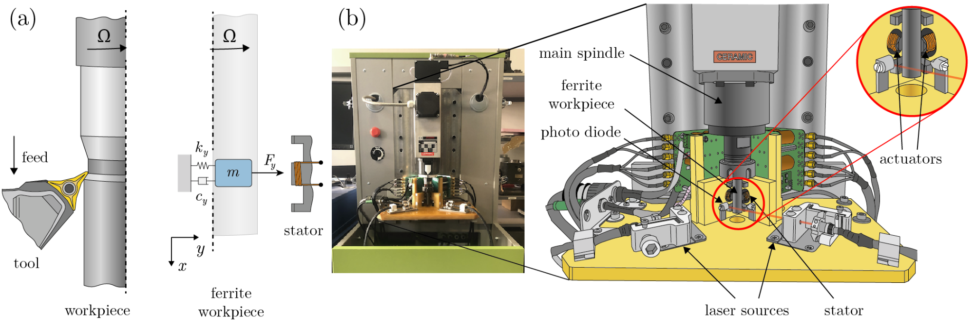
Figure 2: (a) Real and virtual turning operations with a rotating ferrite workpiece and its one degree-of-freedom mechanical model where the workpiece is assumed to be flexible [C3,P3,P4]. (b) Hardware-in-the-loop setup. [P2,P5]
Identification of mechanical parameters
During the research, the spindle speed dependent dynamics of the HIL setup is investigated with the help of sinusoidal sweep excitation achieved by the built-in actuators. In this way, the flexible workpiece [P3,P4] is perturbed in the relevant frequency domain and its response is also monitored [P2,C2,P5]. Using the measurement results, the Frequency Response Functions (FRFs) of the system can be calculated and the spindle speed dependent dynamics can be represented in a Campbell diagram (see Fig. 3) [R7,P2,C2,P5]. Based on this method, the principal modes and the corresponding mechanical parameters of the setup can be identified [P2].
Theoretical stability analysis
The parameter identification provides an opportunity to set up theoretical mechanical models including adaptation of the virtual cutting force. The instantaneous chip thickness depending on the past and the present positions of the cutting tool causes the variation of the cutting force, which leads to delay differential equations [R2]. The investigation also takes into account the effect of the flexibility of the workpiece (or tool) [C3,C4,P3,P4] and/or the nonlinearity of the emulated cutting force [C2,P5]. The stability analysis of the process is performed in the spindle speed–virtual chip width parameter plane [C3,C4]. The determination of the stable parameter pairs can be given both in frequency and time domains by means of the D-subdivision method and/or the semi-discretization method (SD) (see Fig.4) [R8,P2].
Experimental stability analysis (Chatter test)
The stability analysis of the emulated process can be performed without any theoretical models of the machine tool structure. For arbitrary parameter pairs (spindle speeds and virtual chip widths), the scanning procedure is automated and needs no supervision. At each parameter point, the chatter test takes about 3 seconds. By calculating the Fast Fourier Transformation (FFT) of the response of the workpiece, the dominant chatter frequency of the process can be identified [P2,C2,P5].
Results
Experimental identification of the spindle speed dependent dynamics
The spindle speed dependent dynamics of the machine tool is monitored real time by means of the built-in electromagnetic actuators and laser sensors. In Fig. 3(a), the spindle speed dependent frequency response functions (FRFs) of the main spindle can be seen. Based on the measurement results, the dominant frequency of the system is identified around f=3.6 kHz. It varies as the spindle speed increases. The enlarged section of Fig. 3(b) shows that there exists one dominant mode in the spindle speed range of n~0.5–9.0 krpm, which frequency slightly increases with the increase of the spindle speed. In the range of n~9.0–12.0 krpm, a transition between three and then two modes is detected. For n~12.0–18.0 krpm, one mode with approximately constant frequency is identified. Besides the variation of the dominant frequency, the non-trivial change of the damping ratio is also observed in the range of 1-6% (see Fig. 3(c)), which has a non-negligible effect on the stability properties of the system [P2].
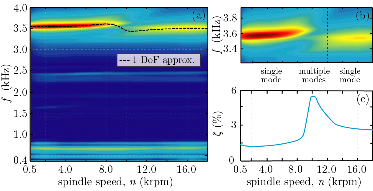
Figure 3: (a) Campbell diagram (spindle speed dependent dynamics). (b) The variation of the dominant frequency of the system. (c) The change in the damping ratio of the dominant one degree-of-freedom (1 DoF) model. [P2,P5]
Experimental and theoretical stability analysis
During the experimental stability analysis, the spindle speed n is varied and the response of the machine is monitored for different virtual specific cutting force coefficients k1=0–1.5k where k is the static stiffness of the spindle. Based on Fig. 4(c), it can be identified that the character of the lower envelope of the measured stability boundary (blue curves) is in agreement with the variation of the damping ratio w.r.t. the spindle speed (see Fig. 3(c) and Fig. 4(a)). The frequency of vibrations arising along the stability boundary is shown in Fig. 4(b). Also, the lower envelope of these frequency curves corresponds to the change of the dominant vibration frequency depicted in Fig. 3(a). The theoretical stability calculation of the emulated material removal process can also be performed by taking into account the spindle speed dependent dynamics of the machine tool. In Fig. 4(c), a simple damped mass-spring oscillator [R4] (see Fig. 2(a)) is used as a one degree-of-freedom (1 DoF) dynamical model. This provides time domain (black curves) and frequency domain (red curves) based theoretical results that are compared with the measured results. The outcome of the theoretical investigation shows quantitative correspondence with the measurements. In case of the time domain analysis (see Fig. 4(c)), the small deviation in the spindle speed range n~9.0–12.0 krpm is explained by the use of the reduced 1 DoF model. The vertical shift in the frequency domain calculation compared to the experimental stability diagram is caused by the additional damping related to the smoothing in the measurement results.
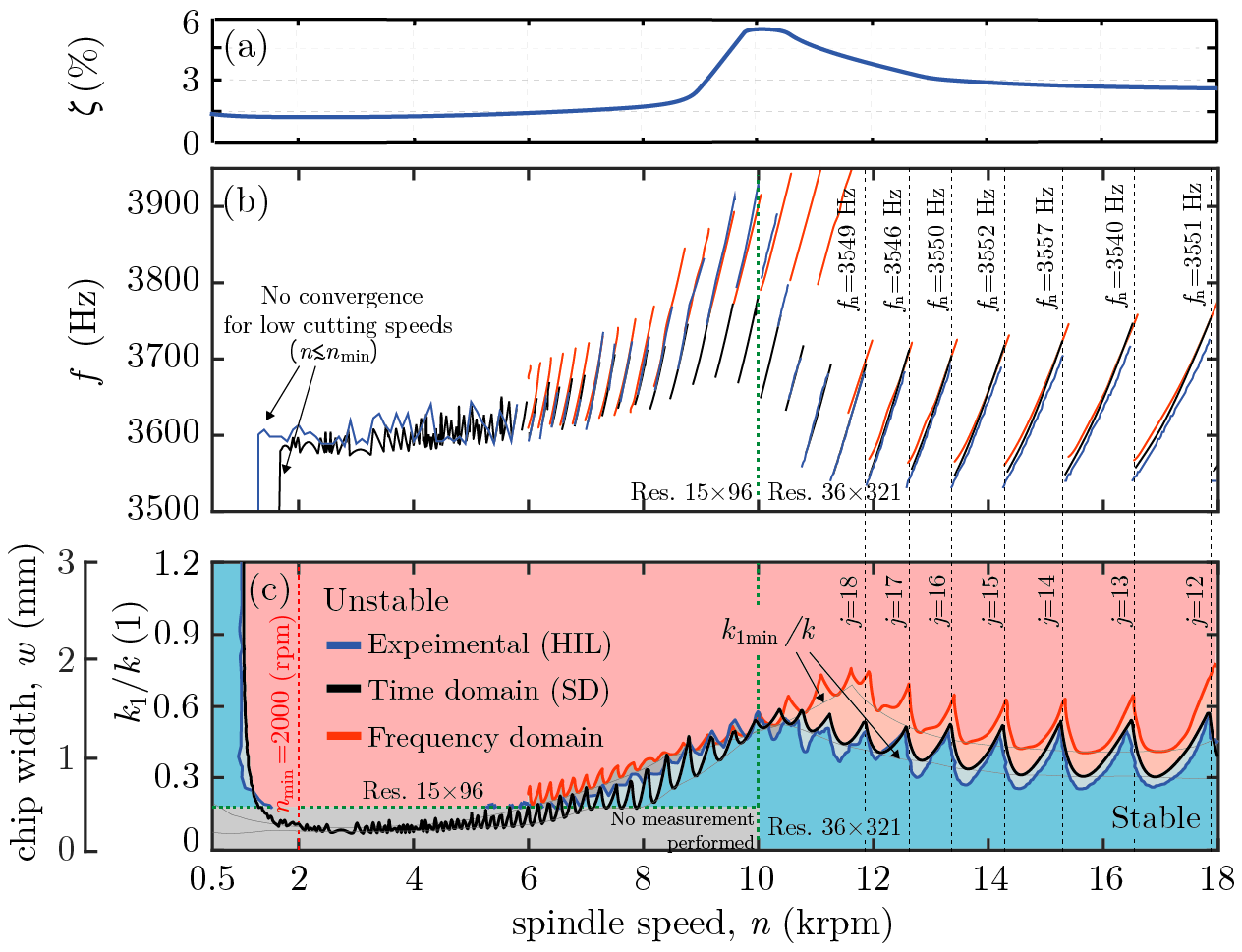
Figure 4: (a) The damping ratio variation of the dominant one degree-of-freedom (1 DoF) model. (b) The frequency of the arising vibrations along the stability boundaries (c) Stability diagrams: hardware-in-the-loop (HIL, blue) and theoretical (time domain - black, frequency domain - red). [P2]
Expected impact and further research
Both the experimental and theoretical results confirm the rationale of the hardware-in-the-loop test rig. The advantage of the experimental stability analysis of the corresponding emulated process is that the measurements are performed under real machine tool conditions without using any theoretical mechanical models. This makes the setup applicable in industrial environment, possibly as a tool installed in CNC machines where the stable parameter region of the system could be analyzed before the real material removal process.
Future research aims also to extend the investigation to milling operations where the stability properties of the process could be further improved by the optimization of the cutting tool geometry. Then the optimized cutting tools can be tested without costly prototyping.
Publications, references, links
List of corresponding own publications
Journal papers
[P1] Beri, B., Stepan, G., Essential chaotic dynamics of chatter in turning processes. Chaos, 30, 053108, 2020. (IF: 2.832)
[P2] Stepan, G., Beri, B., Miklos, A., Wohlfart, R., Bachrathy, D., Porempovics, G., Toth, A., Takacs, D., On stability of emulated turning processes in HIL environment. CIRP Annals, 68(1), 405–408, 2019. (IF: 3.641)
[P3] Beri, B., Stepan, G., Hogan, SJ., Effect of potential energy variation on the natural frequency of an Euler-Bernoulli cantilever beam under lateral force and compression. Journal of Applied Mechanics, 84(5), 051002-1, 2017. (IF: 2.671)
[P4] Beri, B., Hogan, J., Stepan, G., Structural stability of a light rotating beam under combined loads. Acta Mechanica, 228(10), 3735-3740. (IF: 2.102)
[P5] Beri, B., Miklos, A., Takacs, D., Stepan, G., Nonlinearities of hardware-in-the-loop environment affecting turning process emulation. International Journal of Machine Tools and Manufacture. doi.: https://doi.org/10.1016/j.ijmachtools.2020.103611 (In press, IF: 8.019)
Conference papers/Book chapters
[C1] Beri, B., Stepan, G., Approximated dynamics of chatter in turning processes. Nonlinear Dynamics of Structures, Systems and Devices, Springer, 463–470, 2020.
[C2] Beri, B., Miklos, A., Takacs, D., Stepan, G., Nonlinearities of emulated turning process in HIL environment. Procedia CIRP. (Under review)
[C3] Beri, B., Stepan, G., Stability of turning process with tool subjected to compression. Procedia CIRP, 77,179-182, 2018.
[C4] Beri, B., Stepan, G., Axiális és torziós terhelés hatása fúrási folyamatok stabilitására, XIII. Magyar Mechanikai Konferencia (MaMek),27–29 August 2019, Miskolc, Hungary.
Table of links
List of references
[R1] Miklos, A., Takacs, D., Wohlfart, R., Porempovics, G., Molnar, T.G., Bachrathy, D., Toth, A., Stepan, G., The development of high speed virtual milling test. In: ASME 2017 Dynamic Systems and Control Conference, ASME, New York, DSCC2017 - 5217. ISBN 978-0-7918-5828-8.
[R2] Tobias, SA., Machine Tool Vibrations. Blackie and Son Ltd., London, 1965.
[R3] Tlusty, J., Polacek, M., The stability of machine tools against self-excited vibrations in machining. International Research in Production Engineering, ASME, 1, 465–474, 1963.
[R4] Altintas, Y., Manufacturing Automation. University Press Cambridge, UK, 2012.
[R5] Altintas, Y., Brecher, C., Weck, M., Witt, S., Virtual Machine Tool. CIRP Annals, 54(2), 115–138, 2005.
[R6] Comak, A., Budak, E., Modeling dynamics and stability of variable pitch and helix milling tools for development of a design method to maximize chatter stability. Precision Engineering, 47, 459–468, 2017.
[R7] Ewins, DJ., Modal Testing: Theory, Practice and Application. Research Studies Press Ltd., Baldock, Hertfordshire, England, 2000.
[R8] Insperger, T., Stepan, G., Semi-Discretization for Time-Delay Systems. Springer Verlag, New York, 2011.