|
|
BMe Research Grant |
|

Doctoral School of Electrical Engineering
Department of Measurement and Information Systems
Supervisor: Dr. Kollár István
Robust Least Squares Sine Fitting
Introducing the research area
Nowadays signal processing tasks are mostly executed in a digital way using computers. However, the signals in the world are analog. Transition between the two sides is performed by analog-to-digital converters (ADCs). Since many ADCs are produced in standardized production (e.g. automotive products, cellphones), the number of ADC tests to be executed is huge. Consequently, it is crucial that we can run tests in a numerically stable way. The purpose of my research is to find the numerically sensitive parts of sine fitting algorithms, and to ensure robust test evaluation.
Brief introduction of the research place
I performed my research at the Department of Measurement and Information Systems with the support of the Digital Signal Processing Laboratory. At the Department, I participate in the work of an Analog-to-digital converter testing group of three researchers supervised by Professor István Kollár [L1].
History and context of the research
In my research I deal with sine fitting algorithms, with a special emphasis on their numerical properties. The use of these algorithms is necessary in various fields of the science of electrical engineering. For example, the quality of supply in the power system can be characterized by a sinusoidal waveform. In addition, sine waves can be generated with high purity. Therefore, IEEE standards 1241 and 1057 prescribe sinusoidal excitation for testing analog-to-digital converters and digital waveform generators [6], [7]. To provide a measure for the quality of these services, accurate estimation of the parameters of the sinusoidal signal is required. The most widespread method is the Least Squares (LS) sine fitting. This method is defined in the above mentioned standards, too. The algorithm is robust, fast and easily programmable. However, from a numerical point of view, its performance can be significantly improved in various aspects. [1]–[3], [S1].
Research goal, open questions
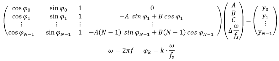
A sampled sine can be described as follows
![]()
where yk is the k-th element of the sampled signal, tk denotes the k-th sampling instant, A, B and C are the cosinusoidal, sinusoidal, and dc components of the signal, respectively, and f denotes the frequency of the signal. Generally, uniform sampling is utilized with the following sampling instants
![]()
where fs is the sampling frequency and N is the record length. In this case
![]()
To describe a sinusoidal signal, four parameters are needed: A, B, C and f/fs. For parameter estimation Least Squares fitting is prescribed in [6]. To get a simpler solution,
![]() is estimated instead of
is estimated instead of
![]() , where
, where
![]() denotes the angular frequency. Thus, the equation system to be solved is
denotes the angular frequency. Thus, the equation system to be solved is

that is
It can be seen from the equation system that while the the first, second and third columns of matrix D contain elements that are bounded between -1 and 1, the absolute value of the elements in the fourth column grow with growing record length. To get a mathematical insight into the problem, the concept of conditioning has to be introduced. In this case, the condition number of the problem is the ratio of the highest singular value of DTD to the lowest one. The condition number upper bounds the error of the Least Squares solution. The higher the condition number, the higher the sensitivity of the solution to small perturbations (e.g., due to roundoff errors [1]). If the condition number can be halved, the worst case relative error of the parameters in the solution vector is also halved. Since the condition number is a ratio, it cannot be decreased beneath 1. Thus, 1 is the optimal condition number. To demonstrate the numerical advantages of a matrix with condition number of 1, it is mentioned here that the condition number of an identity matrix of arbitrary size is 1.
In the research field it is known that the four-parameter Least Squares method is ill-conditioned [8]. To illustrate this, let us consider a purely sinusoidal signal with the following parameters
![]()
Let the record length be N=106. In this case the condition number is cond(DTD)![]() . It can be seen that the problem is ill-conditioned. The aim of the research is to ensure the lowest possible condition number, and this way also to have a numerically stable evaluation.
. It can be seen that the problem is ill-conditioned. The aim of the research is to ensure the lowest possible condition number, and this way also to have a numerically stable evaluation.
Methods
It is obvious that the ill-conditioning is caused by the fourth column of matrix D. The first (and trivial) approach of the problem is to scale the fourth column [1],[8],[9]. This means that each element in the fourth column has to be divided with the same value. This way it is ensured that they have the same order of magnitude as the first three columns. (Naturally, the fourth parameter received after the equation system is solved has to be divided with the same value, in order to get the solution of the same equation system). I have proven [S1] that in case the elements of the fourth column are divided by scaling factor
![]()
then with some approximations, the condition number can be decreased in general to 14.0.
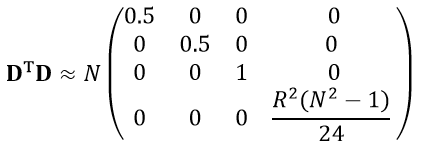
Denoting the scaling factor with 𝛾, the following approximation can be given after scaling
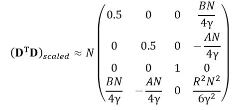
where
![]() . With the above mentioned scaling, a significant improvement in the conditioning can be achieved. Observing the scaled matrix
DTD it can be noticed that the elements of the fourth row and the fourth column can be significantly decreased, but the scaled
DTD does not become diagonal. From a numerical point of view, diagonality would be advantageous. Thus, it should be investigated whether the modification of parameters can enhance the numerical properties of the problem.
. With the above mentioned scaling, a significant improvement in the conditioning can be achieved. Observing the scaled matrix
DTD it can be noticed that the elements of the fourth row and the fourth column can be significantly decreased, but the scaled
DTD does not become diagonal. From a numerical point of view, diagonality would be advantageous. Thus, it should be investigated whether the modification of parameters can enhance the numerical properties of the problem.
As it could be seen in the previous section, the starting point of uniform sampling is usually t=0. However, as data are processed after the whole sampling process has been executed, this instant has no physical meaning. Thus, it is worthy to set t=0 so that it is at the middle of the sampling set. That is, time index goes from -N/2 to N/2 (instead of the standard problem, where it goes from 0 to N-1). In this case symmetrical properties can be exploited. Figure 1 shows the columns of matrix D before and after modification.
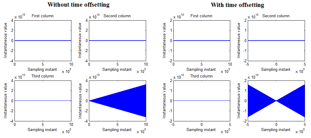
Figure 1. - Columns of matrix D without and with the modification of time axis parameters
Results
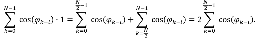
The question is, how much influence the modification of time axis parameters, that is, the offsetting of time instant t=0, has on the numerical properties of the problem. It is important to notice that this modification is really advantageous. Namely, it exploits the odd property of the sine function, and the even property of the cosine function. If DTD has to be calculated in order to determine the condition number, scalar products of the columns of matrix D have to be calculated (that is, corresponding elements have to be multiplied and the products have to be summed). If the columns containing cosine and sine values have to be multiplied, it can be observed that
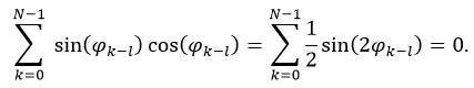
where l=(N-1)/2 is the offset that is subtracted from the time parameter. The reason for the equation is that due to the symmetry of the time axis, the first element is the negative pair of the last element, the second element is the negative pair of the last but first element, etc. Similarly, it can be exploited that cosine is an even function. Thus, if the scalar product of the cosine elements with the dc elements has to be calculated we get
This means that the needed operations can be halved, since only the first N/2 elements have to be determined (here it was assumed that N is even, but for odd Ns a similar formula can be given). Similarly, other elements in DTD can be calculated. The result is [S1]
It can be noticed that
DTD has been made approximately diagonal. It follows that if the third column of D is divided by
![]() , and the fourth column of
D is divided by
, and the fourth column of
D is divided by
![]() , then the following matrix can be obtained
, then the following matrix can be obtained
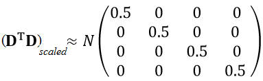
It is trivial that the condition number of this matrix is 1, since all its singular values are equal to 0.5. This means that from a numerical point a view, the approach of the optimal condition number of 1 has been ensured [S1].
Expected impact and further research
As it was mentioned in the introduction, analog-to-digital converters are tested with sine fitting algorithms. Thus, LS sine fitting has to be executed for each converter to be tested, according to IEEE Standard 1241 [6]. In my opinion, the results of my research may extend this standard.
Of my publications [1] and [S1] have been submitted to the IEEE Transactions on Instrumentation and Measurement. This journal is Q1 rated (i.e., it is in the top 25%) by SJR (SCImago Journal & Country Rank) both for ‘Electrical end Electronic Engineering’ and ‘Instrumentation’.
The research is the part of a Hungarian Research Fund (OTKA) project (Investigation of optimal parameter estimation methods, ID: K-115820). Numerical enhancement methods will be built into the freely available MATLAB-toolbox that is developed by my research group, and has been downloaded from more than 10 countries [L1].
Own publications
[1] B. Renczes, I. Kollár, A. Moschitta, P. Carbone, „Numerical Optimization Problems of Sine-Wave Fitting Algorithms in the Presence of Roundoff Errors”, Accepted for publication in IEEE Transactions on Instrumentation and Measurement, 2016, doi: 10.1109/TIM.2016.2562218
[2] B. Renczes, I. Kollár, P. Carbone, A. Moschitta, V. Pálfi, T. Virosztek, “Analyzing Numerical Optimization Problems of Finite Resolution Sine Wave Fitting Algorithms”, Proceedings of IEEE International Instrum. Meas. Technology Conference, pp. 1662–1667, Pisa, Italy, May 11–14, 2015, doi: 10.1109/I2MTC.2015.7151529
[3] B. Renczes, I. Kollár, ”Roundoff Errors in the Evaluation of the Cost Function in Sine Wave Based ADC Testing”, 20th IMEKO TC 4 Symposium and 18th IWADC Workshop, Benevento, Italy, September 15–17, 2014,
URL: http://www.imeko-tc4-2014.org/files/IMEKO_TC4_2014_proceedings.pdf.
[4] B. Renczes, I. Kollár, ”Linearization of A/D converters using interpolation of samples”, 19th IMEKO TC 4 Symposium and 17th IWADC Workshop, Barcelona, Spain, July 18–19., 2013
URL: http://mycite.omikk.bme.hu/doc/144252.pdf
[5] B. Renczes, I. Kollár, “Compensation of Analog-to-Digital Converter Nonlinearities using Dither”, Periodica Polytechnica – Electrical Engineering 57 (3), pp. 77–81, (2013),
doi: 10.3311/PPee.2145
Submitted publications
[S1] B. Renczes, I. Kollár, “Efficient Implementation of Least Squares Sine Fitting Algorithms”, Submitted after major revision to IEEE Transactions on Instrumentation and Measurement
References
[6] Standard IEEE-1241-2010, “IEEE Standard for Terminology and Test Methods for Analog-to-Digital Converters” (2011) doi: 10.1109/IEEESTD.2011.5692956
[7] IEEE Standard-1057-2007, „Standard for Digitizing Waveform Recorders”, 2007
doi: 10.1109/IEEESTD.2008.4494996
[8] P. Ramos, T. Radil, F. Janeiro, “Implementation of sine-fitting algorithms in systems with 32-bit floating point representation”, Measurement 45, pp. 155–163, 2012. doi:10.1016/j.measurement.2011.05.011
[9] K. Chen, Y. Xue, “Improving four-parameter sine wave fitting by normalization”, Computer Standards and Interfaces, vol. 29, pp. 184–190, 2007. doi:10.1016/j.csi.2006.05.005