|
|
BMe Research Grant |
|

Doctoral School of Electrical Engineering
BME VIK, Department of Measurement and Information Systems
Supervisor: Dr. Kollár István
Qualification Support of Analog-to-Digital Converters - An Accurate and Cost-Effective Method for Decreasing Numerical Inaccuracies
Introduction of the research area
Nowadays, signal processing tasks are mostly executed digitally, using computers. However, we can reach the signals of the surrounding world only in an analog way. The transmission between the two sides is performed by analog-to-digital converters (ADCs). Since many ADCs are produced for standardized production (e.g. automotive products, cellphones), the number of applied ADCs is huge. Consequently, it is crucial to be able to run tests in a numerically stable and possibly cheap way. The purpose of my research is to find the numerically sensitive points of sine fitting algorithms that are needed for ADC testing, and to ensure robust test evaluation.
Brief introduction of the research place
I performed my research at the Department of Measurement and Information Systems with the support of the Digital Signal Processing Laboratory. At the Department I am working in an Analog-to-digital converter testing group of three researchers that was supervised by Professor István Kollár († 2016) [L1].
History and context of the research
In a wider sense, the research deals with testing of analog-to-digital converters - as the title shows, as well. Although IEEE Standard 1241 is available for this purpose [8], it is worth investigating whether the criteria that can easily be fulfilled in principle, are feasible in practice, too. My task is to explore and reduce numerical problems, that is, the problems connected with computerized processing. In other words: where are the points in the algorithm exhibiting significantly larger errors than expected, due to computational inaccuracies. Besides, what can be done to reduce these errors?
During analog-to-digital conversion, the analog signals of the surrounding world are converted to digital ones that can be processed by computers. This process is demonstrated in Figure 1. In the course of conversion, the signal that is continuous in time and amplitude is first sampled, and then quantized, that is, it is made discrete in time and space.
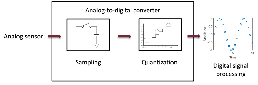
Fig. 1: The process of analog-to-digital conversion
The description of the characteristics of conversion, and their measurement methods are defined in IEEE Standard 1241 [8]. Among these, one of the most important methods is sine fitting. In the course of sine fitting, a purely sinusoidal excitation is applied and it is investigated, how much the output of the converter follows the output of an ideal one.
Research goal, open questions
To run a sine fitting algorithm, applying a purely sinusoidal excitation, a sine wave has to be fitted to the output of the ADC. A uniformly, that is, equidistantly sampled sinusoidal signal can be described generally, as follows:
![]() ,
,
where yk is the kth sample of the sine wave, A, B and C are the amplitudes of cosinusoidal, sinusoidal and DC components, respectively. The frequency of the signal is denoted by f, while fs is the sampling frequency. The phase of sine and cosine functions has to be evaluated at each time instant:
![]() .
.
It can be seen that with increasing k, the value of the instantaneous phase increases, as well. In modern computers, floating point number representation is widely used (it will be covered in detail in section Methods). Applying single precision arithmetic, the relative roundoff errors are in the order of magnitude of 10-7.
The exact absolute roundoff errors of
![]() are
depicted in Figure 2 (when
are
depicted in Figure 2 (when
![]()
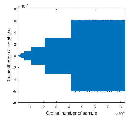
Fig. 2: Error of phase evaluation with single precision number representation
Naturally, if double precision number representation was applied, the magnitude of errors would be much smaller. Still it is worth investigating single precision representation, because we may want to realize the same algorithm on limited precision equipment that is consequently cheaper. The research tries to find an answer to the question: how the error of phase evaluation related inaccuracies can be reduced, thus supporting single precision signal processing.
Methods
As we saw in the previous section, modern signal processing units often apply floating point number representation. The reason is the wide dynamic range it can cover with approximately constant relative errors. In floating point representation, the number is given in normalized form, similarly to the scientific function of calculators. For instance,
![]() ,
,
that is, we have a number (mantissa, in this case 1.56343) that has to be multiplied with the adequate power (exponent, in this case -5) of 10, in order to get the number to be represented. The advantage of the method is that there is no need to store many zeroes. Thus, with the exponent, we can represent numbers in a wide dynamic range. Since the mantissa can be stored only on finite length (in this case the mantissa length equals to 6), roundoff error occurs at the storage. This influences the last digit of the mantissa, but its magnitude depends on the exponent. The larger the exponent, that is, the mantissa has to be multiplied by the larger power of 10, the larger the absolute value of the roundoff error. However, and this is the advantage of the method, the maximal relative roundoff error is constant in the whole range of representable numbers. In computers, the relative roundoff errors of single precision representation are in the order of magnitude of 10-7, while for double precision, they are in the order of magnitude of 10-16. In the former case 4, while in the latter case, 8 bytes are needed to store a floating point number.
It is clear that the problem is caused by fact that the absolute value of the phase increases with increasing number of samples. If this increase could be limited, the roundoff error would be upper bounded, as well. Namely, the roundoff error is proportional to the absolute value of the represented number.
The limitation of the absolute value of the phase can be performed easily.
Namely, this information is utilized as the argument of sine and cosine
functions. These are periodic functions with
![]() .
Thus, if the fractional phase information is evaluated according to formula
.
Thus, if the fractional phase information is evaluated according to formula
![]()
Where
![]()
![]()
![]()
We should emphasize here that the calculation of the fractional part should be performed prior to the calculation of fk/fs. Namely, if this latter calculation is performed, the result has to be stored, and in this case, the original large roundoff errors occur. After the storage, the subtraction of the integer part has no effect, since precise phase information was already lost. Thus, it is important to intervene before storing the result. To this aim, incremental phase evaluation can be applied [1]. In this method, the fractional phase is calculated as
![]() .
.
Consequently, for the calculation of the fractional phase at the next time
instant, the result of the current time instant is utilized – hence the name
incremental calculation. At the calculation of the fractional part, it has to
be examined, whether the result is greater than 0.5. If it is, 1 has to be
subtracted from the result to obtain the fractional part. By this means, it is
ensured that the result is mapped in range
![]()
Unfortunately, the problem is not completely solved yet. Namely, in case of floating point number representation, the error of summation is not 0, either. For instance, applying single precision arithmetic
![]() ,
,
that is, the result is not even approximately the expected 0. In order to overcome this issue, a compensated summation technique, suggested by Kahan, can be used [10]. This summation compensates at each summation step with the error of the previous summation step. Incremental phase calculation, supplemented with compensated summation is capable of reducing roundoff errors significantly.
Results
To
demonstrate the significance of reducing the error of phase evaluation, a
Monte Carlo
analysis
was carried out. For this purpose, 100,000 different
![]()
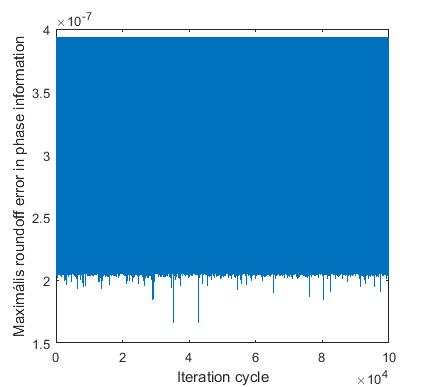
Fig. 3: Maximum error of phase evaluation in the Monte Carlo analysis, applying incremental phase calculation [1]
Although the error of phase calculation was reduced, it is reasonable to investigate how much impact this has on practical applications, such as the testing of ADCs. To this aim, let us introduce the concept of effective number of bits (ENOB). The ENOB value determines how many bits from the nominal bit number can be used in practice. If a nominally 16-bit ADC has an ENOB of 14, this means that due to different non-idealities (harmonic distortion, noisy conversion), the error at the output is so large that the two bits, ensuring the finest resolution, do not give extra information about the input signal.
The effect of the roundoff errors in phase calculation can be demonstrated as follows. Let us take an ideal 12-bit ADC. The ENOB of this converter is 12, as well. Let us generate 100 sinusoidal excitation, and let us investigate, what ENOB value is calculated from the digitized signal. First, double precision and single precision number representation was applied. Furthermore, the evaluation was performed with single precision, applying the proposed algorithm that reduces the error of phase evaluation. Mean ENOB values are delineated in Table 1.
|
Number of samples |
Double precision evaluation |
Single precision evaluation |
Single precision evaluation with reducing the error of phase calculation |
|
10 000 |
12.00 |
11.97 |
12.00 |
|
25 000 |
12.00 |
11.81 |
12.00 |
|
50 000 |
12.00 |
11.43 |
12.00 |
|
100 000 |
12.00 |
10.74 |
12.00 |
Table 1 - Mean ENOB values applying different evaluations
For 10,000 samples, the differences can be neglected. However, with increasing sample sizes, the differences between double and single precision calculations grow, as well. For 100,000 samples, the difference is more than 1 bit in the ENOB value. This error originates primarily from imprecise phase calculation. Namely, applying single precision evaluation with reducing the error of phase calculation, the error of the ENOB values becomes negligible.
Hence, with the help of the proposed method, the ENOB value can be evaluated precisely even on devices with single precision. It means that applying extra signal processing steps, the cost of required hardware can be reduced significantly. Furthermore, it should be emphasized that the algorithm was only modified at points where the inaccuracies due to roundoff errors are critical. By this means, the evaluation time of calculation is not increased unlimited.
Expected impact and further research
The testing of analog-to-digital converters is (among others) performed with the help of sine fitting algorithms. Accordingly, a sine wave fitting has to be performed on each device to be tested, based on IEEE Standard 1241. Consequently, it is important that besides numerical stability, the algorithms can be performed in a cost-effective way. The results of the research enable a significant reduction in the sufficient hardware costs by inserting extra computational steps.
Among my publications, [1], [2] and [3] were submitted to the renowned journal of IEEE Transactions on Instrumentation and Measurement. This journal is rated as Q1 (that is, it is in the top 25%) by SJR (SCImago Journal & Country Rank) in research areas of both ’Electrical and Electronic Engineering’ and ’Instrumentation’.
The research is the part of a Hungarian Research Fund (OTKA) project (Investigation of optimal parameter estimation methods, ID: K-115820), initiated by Professor István Kollár. As recognition of my research, the PhD Grant was awarded to me by the Pro Progressio Foundation.
Numerical enhancement methods are planned to be built into the freely available MATLAB toolbox developed by the research group. This tool has already been downloaded from more than 10 countries from all around the world [L1].
Own publications
[1] B. Renczes, “Accurate Floating Point Argument Calculation for Sine Fitting Algorithms”, Accepted subject to minor revisions in IEEE Transactions on Instrumentation and Measurement, 2017
[2] B. Renczes, I. Kollár, A. Moschitta, P. Carbone, „Numerical Optimization Problems of Sine-Wave Fitting Algorithms in the Presence of Roundoff Errors”, IEEE Transactions on Instrumentation and Measurement, vol. 65, no. 8., pp. 1785-1795, 2016, doi: 10.1109/TIM.2016.2562218
[3] B. Renczes, I. Kollár, “Efficient Implementation of Least Squares Sine Fitting Algorithms”, IEEE Transactions on Instrumentation and Measurement, vol. 65., no. 12., pp. 2717-2724, doi: 10.1109/TIM.2016.2600998
[4] B. Renczes, I. Kollár, P. Carbone, A. Moschitta, V. Pálfi, T. Virosztek, “Analyzing Numerical Optimization Problems of Finite Resolution Sine Wave Fitting Algorithms”, Proceedings of IEEE International Instrum. Meas. Technology Conference, pp. 1662-1667, Pisa, Italy, May 11-14, 2015, doi: 10.1109/I2MTC.2015.7151529
[5] B. Renczes, I. Kollár, ”Roundoff Errors in the Evaluation of the Cost Function in Sine Wave Based ADC Testing”, 20th IMEKO TC 4 Symposium and 18th IWADC Workshop, Benevento, Italy, September 15-17, 2014,
URL: http://www.imeko-tc4-2014.org/files/IMEKO_TC4_2014_proceedings.pdf.
[6] B. Renczes, I. Kollár, ”Linearization of A/D converters using interpolation of samples”, 19th IMEKO TC 4 Symposium and 17th IWADC Workshop, Barcelona, Spain, July 18-19., 2013
URL: http://mycite.omikk.bme.hu/doc/144252.pdf
[7] B. Renczes, I. Kollár, “Compensation of Analog-to-Digital Converter Nonlinearities using Dither”, Periodica Polytechnica – Electrical Engineering 57 (3), pp. 77-81, (2013),
doi: 10.3311/PPee.2145
References
[8] Standard IEEE-1241-2010, “IEEE Standard for Terminology and Test Methods for Analog-to-Digital Converters” (2011) doi: 10.1109/IEEESTD.2011.5692956
[9] IEEE Standard-754-2008, „IEEE Standard for Floating-Point Arithmetic”, 2008
doi: 10.1109/IEEESTD.2008.4610935
[10] W. Kahan, “Further remarks on reducing truncation errors”, Communications of the ACM, vol. 8, no. 1: p. 40, 1965, doi: 10.1145/363707.363723
Links
[L1] I. Kollár, T. Virosztek, V. Pálfi, B. Renczes, “ADCTest Project”
http://www.mit.bme.hu/projects/adctest